pyFAI Package
- pyFAI.__init__.benchmarks(*arg, **kwarg)
Run the integrated benchmarks.
See the documentation of pyFAI.benchmark.run_benchmark
- pyFAI.__init__.tests(deprecation=False)
Runs the test suite of the installed version
Parameters: deprecation – enable/disables deprecation warning in the tests
average Module
Utilities, mainly for image treatment
- exception pyFAI.average.AlgorithmCreationError
Bases: exceptions.RuntimeError
Exception returned if creation of an ImageReductionFilter is not possible
- class pyFAI.average.Average
Bases: object
Process images to generate an average using different algorithms.
- __init__()
Constructor
- add_algorithm(algorithm)
Defines another algorithm which will be computed on the source.
Parameters: algorithm (ImageReductionFilter) – An averaging algorithm.
- get_counter_frames()
Returns the number of frames used for the process.
Return type: int
- get_fabio_images()
Returns source images as fabio images.
Return type: list(fabio.fabioimage.FabioImage)
- get_image_reduction(algorithm)
Returns the result of an algorithm. The process must be already done.
Parameters: algorithm (ImageReductionFilter) – An averaging algorithm Return type: numpy.ndarray
- process()
Process source images to all defined averaging algorithms defined using defined parameters. To access to the results you have to define a writer (AverageWriter). To follow the process forward you have to define an observer (AverageObserver).
- set_correct_flat_from_dark(correct_flat_from_dark)
Defines if the dark must be applied on the flat.
Parameters: correct_flat_from_dark (bool) – If true, the dark is applied.
- set_dark(dark_list)
Defines images used as dark.
Parameters: dark_list (list) – List of dark used
- set_flat(flat_list)
Defines images used as flat.
Parameters: flat_list (list) – List of dark used
- set_images(image_list)
Defines the set set of source images to used to process an average.
Parameters: image_list (list) – List of filename, numpy arrays, fabio images used as source for the computation.
- set_monitor_name(monitor_name)
Defines the monitor name used to correct images before processing the average. This monitor must be part of the file header, else the image is skipped.
Parameters: monitor_name (str) – Name of the monitor available on the header file
- set_observer(observer)
Set an observer to the average process.
Parameters: observer (AverageObserver) – An observer
- set_pixel_filter(threshold, minimum, maximum)
Defines the filter applied on each pixels of the images before processing the average.
Parameters: - threshold – what is the upper limit? all pixel > max*(1-threshold) are discareded.
- minimum – minimum valid value or True
- maximum – maximum valid value
- set_writer(writer)
Defines the object write which will be used to store the result.
Parameters: writer (AverageWriter) – The writer to use.
- class pyFAI.average.AverageDarkFilter(filter_name, cut_off, quantiles)
Bases: pyFAI.average.ImageStackFilter
Filter based on the algorithm of average_dark
TODO: Must be split according to each filter_name, and removed
- __init__(filter_name, cut_off, quantiles)
- get_parameters()
Return a dictionary containing filter parameters
- name
- class pyFAI.average.AverageObserver
Bases: object
- algorithm_finished(algorithm)
Called when an algorithm is finished
- algorithm_started(algorithm)
Called when an algorithm is started
- frame_processed(algorithm, frame_index, frames_count)
Called after providing a frame to an algorithm
- image_loaded(fabio_image, image_index, images_count)
Called when an input image is loaded
- process_finished()
Called when the full process is finished
- process_started()
Called when the full processing is started
- result_processing(algorithm)
Called before the result of an algorithm is computed
- class pyFAI.average.AverageWriter
Interface for using writer in Average process.
- close()
Close the writer. Must not be used anymore.
- write_header(merged_files, nb_frames, monitor_name)
Write the header of the average
Parameters: - merged_files (list) – List of files used to generate this output
- nb_frames (int) – Number of frames used
- monitor_name (str) – Name of the monitor used. Can be None.
- write_reduction(algorithm, data)
Write one reduction
Parameters: - algorithm (ImageReductionFilter) – Algorithm used
- data (object) – Data of this reduction
- class pyFAI.average.ImageAccumulatorFilter
Bases: pyFAI.average.ImageReductionFilter
Filter applied in a set of images in which it is possible to reduce data step by step into a single merged image.
- add_image(image)
Add an image to the filter.
Parameters: image (numpy.ndarray) – image to add
- get_result()
Get the result of the filter.
Returns: result filter Return type: numpy.ndarray
- init(max_images=None)
- class pyFAI.average.ImageReductionFilter
Bases: object
Generic filter applied in a set of images.
- add_image(image)
Add an image to the filter.
Parameters: image (numpy.ndarray) – image to add
- get_parameters()
Return a dictionary containing filter parameters
Return type: dict
- get_result()
Get the result of the filter.
Returns: result filter
- init(max_images=None)
Initialize the filter before using it.
Parameters: max_images (int) – Max images supported by the filter
- class pyFAI.average.ImageStackFilter
Bases: pyFAI.average.ImageReductionFilter
Filter creating a stack from all images and computing everything at the end.
- add_image(image)
Add an image to the filter.
Parameters: image (numpy.ndarray) – image to add
- get_result()
- init(max_images=None)
- class pyFAI.average.MaxAveraging
Bases: pyFAI.average.ImageAccumulatorFilter
- name = 'max'
- class pyFAI.average.MeanAveraging
Bases: pyFAI.average.SumAveraging
- get_result()
- name = 'mean'
- class pyFAI.average.MinAveraging
Bases: pyFAI.average.ImageAccumulatorFilter
- name = 'min'
- exception pyFAI.average.MonitorNotFound
Bases: exceptions.Exception
Raised when monitor information in not found or is not valid.
- class pyFAI.average.MultiFilesAverageWriter(file_name_pattern, file_format, dry_run=False)
Bases: pyFAI.average.AverageWriter
Write reductions into multi files. File headers are duplicated.
- __init__(file_name_pattern, file_format, dry_run=False)
Parameters: - file_name_pattern (str) – File name pattern for the output files. If it contains “{method_name}”, it is updated for each reduction writing with the name of the reduction.
- file_format (str) – File format used. It is the default extension file.
- dry_run (bool) – If dry_run, the file is created on memory but not saved on the file system at the end
- close()
Close the writer. Must not be used anymore.
- get_fabio_image(algorithm)
Get the constructed fabio image
Return type: fabio.fabioimage.FabioImage
- write_header(merged_files, nb_frames, monitor_name)
- write_reduction(algorithm, data)
- class pyFAI.average.SumAveraging
Bases: pyFAI.average.ImageAccumulatorFilter
- name = 'sum'
- pyFAI.average.average_dark(lstimg, center_method='mean', cutoff=None, quantiles=(0.5, 0.5))
Averages a serie of dark (or flat) images. Centers the result on the mean or the median ... but averages all frames within cutoff*std
Parameters: - lstimg – list of 2D images or a 3D stack
- center_method (str) – is the center calculated by a “mean”, “median”, “quantile”, “std”
- cutoff (float or None) – keep all data where (I-center)/std < cutoff
- quantiles (tuple(float, float) or None) – 2-tuple of floats average out data between the two quantiles
Returns: 2D image averaged
- pyFAI.average.average_images(listImages, output=None, threshold=0.1, minimum=None, maximum=None, darks=None, flats=None, filter_='mean', correct_flat_from_dark=False, cutoff=None, quantiles=None, fformat='edf', monitor_key=None)
- Takes a list of filenames and create an average frame discarding all
- saturated pixels.
Parameters: - listImages – list of string representing the filenames
- output – name of the optional output file
- threshold – what is the upper limit? all pixel > max*(1-threshold) are discareded.
- minimum – minimum valid value or True
- maximum – maximum valid value
- darks – list of dark current images for subtraction
- flats – list of flat field images for division
- filter – can be “min”, “max”, “median”, “mean”, “sum”, “quantiles” (default=’mean’)
- correct_flat_from_dark – shall the flat be re-corrected ?
- cutoff – keep all data where (I-center)/std < cutoff
- quantiles – 2-tuple containing the lower and upper quantile (0<q<1) to average out.
- fformat – file format of the output image, default: edf
- str (monitor_key) – Key containing the monitor. Can be none.
Returns: filename with the data or the data ndarray in case format=None
- pyFAI.average.bounding_box(img)
Tries to guess the bounding box around a valid massif
Parameters: img – 2D array like Returns: 4-typle (d0_min, d1_min, d0_max, d1_max)
- pyFAI.average.common_prefix(string_list)
Return the common prefix of a list of strings
TODO: move it into utils package
Parameters: string_list (list(str)) – List of strings Return type: str
- pyFAI.average.create_algorithm(filter_name, cut_off=None, quantiles=None)
Factory to create algorithm according to parameters
Parameters: - cutoff (float or None) – keep all data where (I-center)/std < cutoff
- quantiles (tuple(float, float) or None) – 2-tuple of floats average out data between the two quantiles
Returns: An algorithm
Return type: ImageReductionFilter
Raises AlgorithmCreationError: If it is not possible to create the algorithm
- pyFAI.average.f
alias of SumAveraging
- pyFAI.average.get_monitor_value(image, monitor_key)
Return the monitor value from an image using an header key.
Parameters: - image (fabio.fabioimage.FabioImage) – Image containing the header
- monitor_key (str) – Key containing the monitor
Returns: returns the monitor else raise an exception
Return type: float
Raises MonitorNotFound: when the expected monitor is not found on the header
- pyFAI.average.is_algorithm_name_exists(filter_name)
Return true if the name is a name of a filter algorithm
- pyFAI.average.remove_saturated_pixel(ds, threshold=0.1, minimum=None, maximum=None)
Remove saturated fixes from an array inplace.
Parameters: - ds – a dataset as ndarray
- threshold (float) – what is the upper limit? all pixel > max*(1-threshold) are discareded.
- minimum (float) – minumum valid value (or True for auto-guess)
- maximum (float) – maximum valid value
Returns: the input dataset
azimuthalIntegrator Module
- class pyFAI.azimuthalIntegrator.AzimuthalIntegrator(dist=1, poni1=0, poni2=0, rot1=0, rot2=0, rot3=0, pixel1=None, pixel2=None, splineFile=None, detector=None, wavelength=None)
Bases: pyFAI.geometry.Geometry
This class is an azimuthal integrator based on P. Boesecke’s geometry and histogram algorithm by Manolo S. del Rio and V.A Sole
All geometry calculation are done in the Geometry class
main methods are:
>>> tth, I = ai.integrate1d(data, npt, unit="2th_deg")
>>> q, I, sigma = ai.integrate1d(data, npt, unit="q_nm^-1", error_model="poisson")
>>> regrouped = ai.integrate2d(data, npt_rad, npt_azim, unit="q_nm^-1")[0]
- DEFAULT_METHOD = 'splitbbox'
- __init__(dist=1, poni1=0, poni2=0, rot1=0, rot2=0, rot3=0, pixel1=None, pixel2=None, splineFile=None, detector=None, wavelength=None)
Parameters: - dist (float) – distance sample - detector plan (orthogonal distance, not along the beam), in meter.
- poni1 (float) – coordinate of the point of normal incidence along the detector’s first dimension, in meter
- poni2 (float) – coordinate of the point of normal incidence along the detector’s second dimension, in meter
- rot1 (float) – first rotation from sample ref to detector’s ref, in radians
- rot2 (float) – second rotation from sample ref to detector’s ref, in radians
- rot3 (float) – third rotation from sample ref to detector’s ref, in radians
- pixel1 (float) – Deprecated. Pixel size of the fist dimension of the detector, in meter. If both pixel1 and pixel2 are not None, detector pixel size is overwritten. Prefer defining the detector pixel size on the provided detector object. Prefer defining the detector pixel size on the provided detector object (detector.pixel1 = 5e-6).
- pixel2 (float) – Deprecated. Pixel size of the second dimension of the detector, in meter. If both pixel1 and pixel2 are not None, detector pixel size is overwritten. Prefer defining the detector pixel size on the provided detector object (detector.pixel2 = 5e-6).
- splineFile (str) – Deprecated. File containing the geometric distortion of the detector. If not None, pixel1 and pixel2 are ignored and detector spline is overwritten. Prefer defining the detector spline manually (detector.splineFile = "file.spline").
- detector (str or pyFAI.Detector) – name of the detector or Detector instance. String description is deprecated. Prefer using the result of the detector factory: pyFAI.detector_factory("eiger4m")
- wavelength (float) – Wave length used in meter
- create_mask(data, mask=None, dummy=None, delta_dummy=None, mode='normal')
Combines various masks into another one.
Parameters: - data (ndarray) – input array of data
- mask (ndarray) – input mask (if none, self.mask is used)
- dummy (float) – value of dead pixels
- delta_dumy – precision of dummy pixels
- mode (str) – can be “normal” or “numpy” (inverted) or “where” applied to the mask
Returns: the new mask
Return type: ndarray of bool
This method combine two masks (dynamic mask from data & dummy and mask) to generate a new one with the ‘or’ binary operation. One can adjust the level, with the dummy and the delta_dummy parameter, when you consider the data values needs to be masked out.
This method can work in two different mode:
- “normal”: False for valid pixels, True for bad pixels
- “numpy”: True for valid pixels, false for others
This method tries to accomodate various types of masks (like valid=0 & masked=-1, ...) and guesses if an input mask needs to be inverted.
- dark_correction(data, dark=None)
Correct for Dark-current effects. If dark is not defined, correct for a dark set by “set_darkfiles”
Parameters: - data – input ndarray with the image
- dark – ndarray with dark noise or None
Returns: 2tuple: corrected_data, dark_actually used (or None)
- darkcurrent
- darkfiles
- empty
- flat_correction(data, flat=None)
Correct for flat field. If flat is not defined, correct for a flat set by “set_flatfiles”
Parameters: - data – input ndarray with the image
- flat – ndarray with flatfield or None for no correction
Returns: 2tuple: corrected_data, flat_actually used (or None)
- flatfield
- flatfiles
- get_darkcurrent()
- get_empty()
- get_flatfield()
- inpainting(data, mask, npt_rad=1024, npt_azim=512, unit='r_m', method='splitpixel', poissonian=False, grow_mask=3)
Re-invent the values of masked pixels
Parameters: - data – input image as 2d numpy array
- mask – masked out pixels array
- npt_rad – number of radial points
- npt_azim – number of azimuthal points
- unit – unit to be used for integration
- method – pathway for integration
- poissonian – If True, add some poisonian noise to the data to make then more realistic
- grow_mask – grow mask in polar coordinated to accomodate pixel splitting algoritm
Returns: inpainting object which contains the restored image as .data
- integrate1d(data, npt, filename=None, correctSolidAngle=True, variance=None, error_model=None, radial_range=None, azimuth_range=None, mask=None, dummy=None, delta_dummy=None, polarization_factor=None, dark=None, flat=None, method='csr', unit=q_nm^-1, safe=True, normalization_factor=1.0, block_size=32, profile=False, all=False, metadata=None)
Calculate the azimuthal integrated Saxs curve in q(nm^-1) by default
Multi algorithm implementation (tries to be bullet proof), suitable for SAXS, WAXS, ... and much more
Parameters: - data (ndarray) – 2D array from the Detector/CCD camera
- npt (int) – number of points in the output pattern
- filename (str) – output filename in 2/3 column ascii format
- correctSolidAngle (bool) – correct for solid angle of each pixel if True
- variance (ndarray) – array containing the variance of the data. If not available, no error propagation is done
- error_model (str) – When the variance is unknown, an error model can be given: “poisson” (variance = I), “azimuthal” (variance = (I-<I>)^2)
- radial_range ((float, float), optional) – The lower and upper range of the radial unit. If not provided, range is simply (data.min(), data.max()). Values outside the range are ignored.
- azimuth_range ((float, float), optional) – The lower and upper range of the azimuthal angle in degree. If not provided, range is simply (data.min(), data.max()). Values outside the range are ignored.
- mask (ndarray) – array (same size as image) with 1 for masked pixels, and 0 for valid pixels
- dummy (float) – value for dead/masked pixels
- delta_dummy (float) – precision for dummy value
- polarization_factor (float) – polarization factor between -1 (vertical) and +1 (horizontal). 0 for circular polarization or random, None for no correction, True for using the former correction
- dark (ndarray) – dark noise image
- flat (ndarray) – flat field image
- method (str) – can be “numpy”, “cython”, “BBox” or “splitpixel”, “lut”, “csr”, “nosplit_csr”, “full_csr”, “lut_ocl” and “csr_ocl” if you want to go on GPU. To Specify the device: “csr_ocl_1,2”
- unit (pyFAI.units.Unit) – Output units, can be “q_nm^-1”, “q_A^-1”, “2th_deg”, “2th_rad”, “r_mm” for now
- safe (bool) – Do some extra checks to ensure LUT/CSR is still valid. False is faster.
- normalization_factor (float) – Value of a normalization monitor
- block_size – size of the block for OpenCL integration (unused?)
- profile – set to True to enable profiling in OpenCL
- all (bool) – if true return a dictionary with many more parameters (deprecated, please refer to the documentation of Integrate1dResult).
- metadata – JSON serializable object containing the metadata, usually a dictionary.
Returns: q/2th/r bins center positions and regrouped intensity (and error array if variance or variance model provided), uneless all==True.
Return type: Integrate1dResult, dict
- integrate2d(data, npt_rad, npt_azim=360, filename=None, correctSolidAngle=True, variance=None, error_model=None, radial_range=None, azimuth_range=None, mask=None, dummy=None, delta_dummy=None, polarization_factor=None, dark=None, flat=None, method='bbox', unit=q_nm^-1, safe=True, normalization_factor=1.0, all=False, metadata=None)
Calculate the azimuthal regrouped 2d image in q(nm^-1)/chi(deg) by default
Multi algorithm implementation (tries to be bullet proof)
Parameters: - data (ndarray) – 2D array from the Detector/CCD camera
- npt_rad (int) – number of points in the radial direction
- npt_azim (int) – number of points in the azimuthal direction
- filename (str) – output image (as edf format)
- correctSolidAngle (bool) – correct for solid angle of each pixel if True
- variance (ndarray) – array containing the variance of the data. If not available, no error propagation is done
- error_model (str) – When the variance is unknown, an error model can be given: “poisson” (variance = I), “azimuthal” (variance = (I-<I>)^2)
- radial_range ((float, float), optional) – The lower and upper range of the radial unit. If not provided, range is simply (data.min(), data.max()). Values outside the range are ignored.
- azimuth_range ((float, float), optional) – The lower and upper range of the azimuthal angle in degree. If not provided, range is simply (data.min(), data.max()). Values outside the range are ignored.
- mask (ndarray) – array (same size as image) with 1 for masked pixels, and 0 for valid pixels
- dummy (float) – value for dead/masked pixels
- delta_dummy (float) – precision for dummy value
- polarization_factor (float) – polarization factor between -1 (vertical) and +1 (horizontal). 0 for circular polarization or random, None for no correction
- dark (ndarray) – dark noise image
- flat (ndarray) – flat field image
- method (str) – can be “numpy”, “cython”, “BBox” or “splitpixel”, “lut”, “csr; “lut_ocl” and “csr_ocl” if you want to go on GPU. To Specify the device: “csr_ocl_1,2”
- unit (pyFAI.units.Unit) – Output units, can be “q_nm^-1”, “q_A^-1”, “2th_deg”, “2th_rad”, “r_mm” for now
- safe (bool) – Do some extra checks to ensure LUT is still valid. False is faster.
- normalization_factor (float) – Value of a normalization monitor
- all (bool) – if true, return many more intermediate results as a dict (deprecated, please refer to the documentation of Integrate2dResult).
- metadata – JSON serializable object containing the metadata, usually a dictionary.
Returns: azimuthaly regrouped intensity, q/2theta/r pos. and chi pos.
Return type: Integrate2dResult, dict
- integrate_radial(data, npt, npt_rad=100, correctSolidAngle=True, radial_range=None, azimuth_range=None, mask=None, dummy=None, delta_dummy=None, polarization_factor=None, dark=None, flat=None, method='csr', unit=chi_deg, radial_unit=q_nm^-1, normalization_factor=1.0)
Calculate the radial integrated profile curve as I = f(chi)
Parameters: - data (ndarray) – 2D array from the Detector/CCD camera
- npt (int) – number of points in the output pattern
- npt_rad (int) – number of points in the radial space. Too few points may lead to huge rounding errors.
- filename (str) – output filename in 2/3 column ascii format
- correctSolidAngle (bool) – correct for solid angle of each pixel if True
- radial_range (Tuple(float, float)) – The lower and upper range of the radial unit. If not provided, range is simply (data.min(), data.max()). Values outside the range are ignored. Optional.
- azimuth_range (Tuple(float, float)) – The lower and upper range of the azimuthal angle in degree. If not provided, range is simply (data.min(), data.max()). Values outside the range are ignored. Optional.
- mask (ndarray) – array (same size as image) with 1 for masked pixels, and 0 for valid pixels
- dummy (float) – value for dead/masked pixels
- delta_dummy (float) – precision for dummy value
- polarization_factor (float) – polarization factor between -1 (vertical) and +1 (horizontal). * 0 for circular polarization or random, * None for no correction, * True for using the former correction
- dark (ndarray) – dark noise image
- flat (ndarray) – flat field image
- method (str) – can be “numpy”, “cython”, “BBox” or “splitpixel”, “lut”, “csr”, “nosplit_csr”, “full_csr”, “lut_ocl” and “csr_ocl” if you want to go on GPU. To Specify the device: “csr_ocl_1,2”
- unit (pyFAI.units.Unit) – Output units, can be “chi_deg” or “chi_rad”
- radial_unit (pyFAI.units.Unit) – unit used for radial representation, can be “q_nm^-1”, “q_A^-1”, “2th_deg”, “2th_rad”, “r_mm” for now
- normalization_factor (float) – Value of a normalization monitor
Returns: chi bins center positions and regrouped intensity
Return type: Integrate1dResult
- medfilt1d(data, npt_rad=1024, npt_azim=512, correctSolidAngle=True, polarization_factor=None, dark=None, flat=None, method='splitpixel', unit=q_nm^-1, percentile=50, mask=None, normalization_factor=1.0, metadata=None)
Perform the 2D integration and filter along each row using a median filter
Parameters: - data – input image as numpy array
- npt_rad – number of radial points
- npt_azim – number of azimuthal points
- correctSolidAngle (bool) – correct for solid angle of each pixel if True
- polarization_factor (float) – polarization factor between -1 (vertical) and +1 (horizontal). 0 for circular polarization or random, None for no correction, True for using the former correction
- dark (ndarray) – dark noise image
- flat (ndarray) – flat field image
- unit – unit to be used for integration
- method – pathway for integration and sort
- percentile – which percentile use for cutting out percentil can be a 2-tuple to specify a region to average out
- mask – masked out pixels array
- normalization_factor (float) – Value of a normalization monitor
- metadata (JSON serializable dict) – any other metadata,
Returns: Integrate1D like result like
- reset()
Reset azimuthal integrator in addition to other arrays.
- save1D(*arg, **kw)
decorator that deprecates the use of a function
- save2D(*arg, **kw)
decorator that deprecates the use of a function
- saxs(*arg, **kw)
decorator that deprecates the use of a function
- separate(data, npt_rad=1024, npt_azim=512, unit='2th_deg', method='splitpixel', percentile=50, mask=None, restore_mask=True)
Separate bragg signal from powder/amorphous signal using azimuthal integration, median filering and projected back before subtraction.
Parameters: - data – input image as numpy array
- npt_rad – number of radial points
- npt_azim – number of azimuthal points
- unit – unit to be used for integration
- method – pathway for integration and sort
- percentile – which percentile use for cutting out
- mask – masked out pixels array
- restore_mask – masked pixels have the same value as input data provided
Returns: bragg, amorphous
- set_darkcurrent(dark)
- set_darkfiles(files=None, method='mean')
Moved to Detector
Parameters: - files (str or list(str) or None) – file(s) used to compute the dark.
- method (str) – method used to compute the dark, “mean” or “median”
Set the dark current from one or mutliple files, avaraged according to the method provided
- set_empty(value)
- set_flatfield(flat)
- set_flatfiles(files, method='mean')
Moved to Detector
Parameters: - files (str or list(str) or None) – file(s) used to compute the flat-field.
- method (str) – method used to compute the dark, “mean” or “median”
Set the flat field from one or mutliple files, averaged according to the method provided
- setup_CSR(shape, npt, mask=None, pos0_range=None, pos1_range=None, mask_checksum=None, unit=2th_deg, split='bbox')
Prepare a look-up-table
Parameters: - shape ((int, int)) – shape of the dataset
- npt (int or (int, int)) – number of points in the the output pattern
- mask (ndarray) – array with masked pixel (1=masked)
- pos0_range ((float, float)) – range in radial dimension
- pos1_range ((float, float)) – range in azimuthal dimension
- mask_checksum (int (or anything else ...)) – checksum of the mask buffer
- unit (pyFAI.units.Unit) – use to propagate the LUT object for further checkings
- split – Splitting scheme: valid options are “no”, “bbox”, “full”
This method is called when a look-up table needs to be set-up. The shape parameter, correspond to the shape of the original datatset. It is possible to customize the number of point of the output histogram with the npt parameter which can be either an integer for an 1D integration or a 2-tuple of integer in case of a 2D integration. The LUT will have a different shape: (npt, lut_max_size), the later parameter being calculated during the instanciation of the splitBBoxLUT class.
It is possible to prepare the LUT with a predefine mask. This operation can speedup the computation of the later integrations. Instead of applying the patch on the dataset, it is taken into account during the histogram computation. If provided the mask_checksum prevent the re-calculation of the mask. When the mask changes, its checksum is used to reset (or not) the LUT (which is a very time consuming operation !)
It is also possible to restrain the range of the 1D or 2D pattern with the pos1_range and pos2_range.
The unit parameter is just propagated to the LUT integrator for further checkings: The aim is to prevent an integration to be performed in 2th-space when the LUT was setup in q space.
- setup_LUT(shape, npt, mask=None, pos0_range=None, pos1_range=None, mask_checksum=None, unit=2th_deg)
Prepare a look-up-table
Parameters: - shape ((int, int)) – shape of the dataset
- npt (int or (int, int)) – number of points in the the output pattern
- mask (ndarray) – array with masked pixel (1=masked)
- pos0_range ((float, float)) – range in radial dimension
- pos1_range ((float, float)) – range in azimuthal dimension
- mask_checksum (int (or anything else ...)) – checksum of the mask buffer
- unit (pyFAI.units.Unit) – use to propagate the LUT object for further checkings
This method is called when a look-up table needs to be set-up. The shape parameter, correspond to the shape of the original datatset. It is possible to customize the number of point of the output histogram with the npt parameter which can be either an integer for an 1D integration or a 2-tuple of integer in case of a 2D integration. The LUT will have a different shape: (npt, lut_max_size), the later parameter being calculated during the instanciation of the splitBBoxLUT class.
It is possible to prepare the LUT with a predefine mask. This operation can speedup the computation of the later integrations. Instead of applying the patch on the dataset, it is taken into account during the histogram computation. If provided the mask_checksum prevent the re-calculation of the mask. When the mask changes, its checksum is used to reset (or not) the LUT (which is a very time consuming operation !)
It is also possible to restrain the range of the 1D or 2D pattern with the pos1_range and pos2_range.
The unit parameter is just propagated to the LUT integrator for further checkings: The aim is to prevent an integration to be performed in 2th-space when the LUT was setup in q space.
- sigma_clip(data, npt_rad=1024, npt_azim=512, correctSolidAngle=True, polarization_factor=None, dark=None, flat=None, method='splitpixel', unit=q_nm^-1, thres=3, max_iter=5, mask=None, normalization_factor=1.0, metadata=None)
Perform the 2D integration and perform a sigm-clipping iterative filter along each row. see the doc of scipy.stats.sigmaclip for the options.
Parameters: - data – input image as numpy array
- npt_rad – number of radial points
- npt_azim – number of azimuthal points
- correctSolidAngle (bool) – correct for solid angle of each pixel if True
- polarization_factor (float) – polarization factor between -1 (vertical) and +1 (horizontal). 0 for circular polarization or random, None for no correction, True for using the former correction
- dark (ndarray) – dark noise image
- flat (ndarray) – flat field image
- unit – unit to be used for integration
- method – pathway for integration and sort
- thres – cut-off for n*sigma: discard any values with (I-<I>)/sigma > thres. The threshold can be a 2-tuple with sigma_low and sigma_high.
- max_iter – maximum number of iterations :param mask: masked out pixels array
- normalization_factor (float) – Value of a normalization monitor
- metadata (JSON serializable dict) – any other metadata,
Returns: Integrate1D like result like
- xrpd(*arg, **kw)
decorator that deprecates the use of a function
- xrpd2(*arg, **kw)
decorator that deprecates the use of a function
- xrpd2_histogram(*arg, **kw)
decorator that deprecates the use of a function
- xrpd2_numpy(*arg, **kw)
decorator that deprecates the use of a function
- xrpd2_splitBBox(*arg, **kw)
decorator that deprecates the use of a function
- xrpd2_splitPixel(*arg, **kw)
decorator that deprecates the use of a function
- xrpd_CSR_OCL(*arg, **kw)
decorator that deprecates the use of a function
- xrpd_LUT(*arg, **kw)
decorator that deprecates the use of a function
- xrpd_LUT_OCL(*arg, **kw)
decorator that deprecates the use of a function
- xrpd_OpenCL(*arg, **kw)
decorator that deprecates the use of a function
- xrpd_cython(*arg, **kw)
decorator that deprecates the use of a function
- xrpd_numpy(*arg, **kw)
decorator that deprecates the use of a function
- xrpd_splitBBox(*arg, **kw)
decorator that deprecates the use of a function
- xrpd_splitPixel(*arg, **kw)
decorator that deprecates the use of a function
multi_geometry Module
Module for treating simultaneously multiple detector configuration within a single integration
- class pyFAI.multi_geometry.MultiGeometry(ais, unit='2th_deg', radial_range=(0, 180), azimuth_range=(-180, 180), wavelength=None, empty=0.0, chi_disc=180)
Bases: object
This is an Azimuthal integrator containing multiple geometries, for example when the detector is on a goniometer arm
- __init__(ais, unit='2th_deg', radial_range=(0, 180), azimuth_range=(-180, 180), wavelength=None, empty=0.0, chi_disc=180)
Constructor of the multi-geometry integrator :param ais: list of azimuthal integrators :param radial_range: common range for integration :param azimuthal_range: common range for integration :param empty: value for empty pixels :param chi_disc: if 0, set the chi_discontinuity at
- integrate1d(lst_data, npt=1800, correctSolidAngle=True, lst_variance=None, error_model=None, polarization_factor=None, normalization_factor=None, all=False, lst_mask=None, lst_flat=None)
Perform 1D azimuthal integration
Parameters: - lst_data – list of numpy array
- npt – number of points int the integration
- correctSolidAngle – correct for solid angle (all processing are then done in absolute solid angle !)
- lst_variance (list of ndarray) – list of array containing the variance of the data. If not available, no error propagation is done
- error_model (str) – When the variance is unknown, an error model can be given: “poisson” (variance = I), “azimuthal” (variance = (I-<I>)^2)
- polarization_factor – Apply polarization correction ? is None: not applies. Else provide a value from -1 to +1
- normalization_factor – normalization monitors value (list of floats)
- all – return a dict with all information in it (deprecated, please refer to the documentation of Integrate1dResult).
- lst_mask – numpy.Array or list of numpy.array which mask the lst_data.
- lst_flat – numpy.Array or list of numpy.array which flat the lst_data.
Returns: 2th/I or a dict with everything depending on “all”
Return type: Integrate1dResult, dict
- integrate2d(lst_data, npt_rad=1800, npt_azim=3600, correctSolidAngle=True, lst_variance=None, error_model=None, polarization_factor=None, normalization_factor=None, all=False, lst_mask=None, lst_flat=None)
Performs 2D azimuthal integration of multiples frames, one for each geometry
Parameters: - lst_data – list of numpy array
- npt – number of points int the integration
- correctSolidAngle – correct for solid angle (all processing are then done in absolute solid angle !)
- lst_variance (list of ndarray) – list of array containing the variance of the data. If not available, no error propagation is done
- error_model (str) – When the variance is unknown, an error model can be given: “poisson” (variance = I), “azimuthal” (variance = (I-<I>)^2)
- polarization_factor – Apply polarization correction ? is None: not applies. Else provide a value from -1 to +1
- normalization_factor – normalization monitors value (list of floats)
- all – return a dict with all information in it (deprecated, please refer to the documentation of Integrate2dResult).
- lst_mask – numpy.Array or list of numpy.array which mask the lst_data.
- lst_flat – numpy.Array or list of numpy.array which flat the lst_data.
Returns: I/2th/chi or a dict with everything depending on “all”
Return type: Integrate2dResult, dict
- set_wavelength(value)
Changes the wavelength of a group of azimuthal integrators
integrate_widget Module
pyFAI-integrate
A graphical tool for performing azimuthal integration on series of files.
- class pyFAI.integrate_widget.AIWidget(input_data=None, output_path=None, output_format=None, slow_dim=None, fast_dim=None, json_file='.azimint.json')
Bases: PyQt4.QtGui.QWidget
- URL = 'http://pyfai.readthedocs.org/en/latest/man/pyFAI-integrate.html'
- __init__(input_data=None, output_path=None, output_format=None, slow_dim=None, fast_dim=None, json_file='.azimint.json')
- assign_unit()
assign unit to the corresponding widget
- detector_changed()
- die()
- dump(filename=None)
Dump the status of the current widget to a file in JSON
Parameters: filename (string) – path where to save the config Returns: dict with configuration
- get_config()
Read the configuration of the plugin and returns it as a dictionary
Returns: dict with all information.
- get_method()
Return the method name for azimuthal intgration
- help()
- openCL_changed()
- platform_changed()
- proceed()
- restore(filename='.azimint.json')
Restore from JSON file the status of the current widget
Parameters: filename (str) – path where the config was saved
- save_config()
- select_darkcurrent()
- select_flatfield()
- select_maskfile()
- select_ponifile()
- select_splinefile()
- setStackDataObject(stack, stack_name=None)
- set_config(dico)
Setup the widget from its description
Parameters: dico (dict) – dictionary with description of the widget
- set_input_data(stack, stack_name=None)
- set_ponifile(ponifile=None)
- set_validators()
Set all validators for text entries
geometry Module
This modules contains only one (large) class in charge of:
- calculating the geometry, i.e. the position in the detector space of each pixel of the detector
- manages caches to store intermediate results
- class pyFAI.geometry.Geometry(dist=1, poni1=0, poni2=0, rot1=0, rot2=0, rot3=0, pixel1=None, pixel2=None, splineFile=None, detector=None, wavelength=None)
Bases: object
This class is an azimuthal integrator based on P. Boesecke’s geometry and histogram algorithm by Manolo S. del Rio and V.A Sole
Detector is assumed to be corrected from “raster orientation” effect. It is not addressed here but rather in the Detector object or at read time. Considering there is no tilt:
- Detector fast dimension (dim2) is supposed to be horizontal (dimension X of the image)
- Detector slow dimension (dim1) is supposed to be vertical, upwards (dimension Y of the image)
- The third dimension is chose such as the referential is orthonormal, so dim3 is along incoming X-ray beam
Demonstration of the equation done using Mathematica:
Axis 1 is allong first dimension of detector (when not tilted), this is the slow dimension of the image array in C or Y In[5]:= x1={1,0,0} Out[5]= {1,0,0} Axis 2 is allong second dimension of detector (when not tilted), this is the fast dimension of the image in C or X In[6]:= x2={0,1,0} Out[6]= {0,1,0} Axis 3 is along the incident X-Ray beam In[7]:= x3={0,0,1} Out[7]= {0,0,1} In[9]:= id3={x1,x2,x3} Out[9]= {{1,0,0},{0,1,0},{0,0,1}} In[10]:= {{1,0,0},{0,1,0},{0,0,1}} Out[10]= {{1,0,0},{0,1,0},{0,0,1}} In[11]:= rotM1=RotationMatrix[rot1,x1] Out[11]= {{1,0,0},{0,Cos[rot1],-Sin[rot1]},{0,Sin[rot1],Cos[rot1]}} In[12]:= rotM2 = RotationMatrix[rot2,x2] Out[12]= {{Cos[rot2],0,Sin[rot2]},{0,1,0},{-Sin[rot2],0,Cos[rot2]}} In[13]:= rotM3 = RotationMatrix[rot3,x3] Out[13]= {{Cos[rot3],-Sin[rot3],0},{Sin[rot3],Cos[rot3],0},{0,0,1}} Rotations of the detector are applied first Rot around axis 1, then axis 2 and finally around axis 3 In[14]:= R=rotM3.rotM2.rotM1 Out[14]= {{Cos[rot2] Cos[rot3],Cos[rot3] Sin[rot1] Sin[rot2]-Cos[rot1] Sin[rot3],Cos[rot1] Cos[rot3] Sin[rot2]+Sin[rot1] Sin[rot3]},{Cos[rot2] Sin[rot3],Cos[rot1] Cos[rot3]+Sin[rot1] Sin[rot2] Sin[rot3],-Cos[rot3] Sin[rot1]+Cos[rot1] Sin[rot2] Sin[rot3]},{-Sin[rot2],Cos[rot2] Sin[rot1],Cos[rot1] Cos[rot2]}} In[15]:= CForm[R.x1] Out[15]//CForm= List(Cos(rot2)*Cos(rot3),Cos(rot2)*Sin(rot3),-Sin(rot2)) In[16]:= CForm[R.x2] Out[16]//CForm= List(Cos(rot3)*Sin(rot1)*Sin(rot2) - Cos(rot1)*Sin(rot3),Cos(rot1)*Cos(rot3) + Sin(rot1)*Sin(rot2)*Sin(rot3),Cos(rot2)*Sin(rot1)) In[17]:= CForm[R.x3] Out[17]//CForm= List(Cos(rot1)*Cos(rot3)*Sin(rot2) + Sin(rot1)*Sin(rot3),-(Cos(rot3)*Sin(rot1)) + Cos(rot1)*Sin(rot2)*Sin(rot3),Cos(rot1)*Cos(rot2)) In[18]:= CForm[Det[R]] Out[18]//CForm= Power(Cos(rot1),2)*Power(Cos(rot2),2)*Power(Cos(rot3),2) + Power(Cos(rot2),2)*Power(Cos(rot3),2)*Power(Sin(rot1),2) + Power(Cos(rot1),2)*Power(Cos(rot3),2)*Power(Sin(rot2),2) + Power(Cos(rot3),2)*Power(Sin(rot1),2)*Power(Sin(rot2),2) + Power(Cos(rot1),2)*Power(Cos(rot2),2)*Power(Sin(rot3),2) + Power(Cos(rot2),2)*Power(Sin(rot1),2)*Power(Sin(rot3),2) + Power(Cos(rot1),2)*Power(Sin(rot2),2)*Power(Sin(rot3),2) + Power(Sin(rot1),2)*Power(Sin(rot2),2)*Power(Sin(rot3),2) In[13]:= Any pixel on detector plan at coordianate (d1, d2) in meters. Detector is at z=L In[22]:= P={d1,d2,L} CForm[R.P] Out[22]= {d1,d2,L} Out[23]//CForm= List(d1*Cos(rot2)*Cos(rot3) + d2*(Cos(rot3)*Sin(rot1)*Sin(rot2) - Cos(rot1)*Sin(rot3)) + L*(Cos(rot1)*Cos(rot3)*Sin(rot2) + Sin(rot1)*Sin(rot3)), d1*Cos(rot2)*Sin(rot3) + L*(-(Cos(rot3)*Sin(rot1)) + Cos(rot1)*Sin(rot2)*Sin(rot3)) + d2*(Cos(rot1)*Cos(rot3) + Sin(rot1)*Sin(rot2)*Sin(rot3)),L*Cos(rot1)*Cos(rot2) + d2*Cos(rot2)*Sin(rot1) - d1*Sin(rot2)) In[24]:= t1 = R.P.x1 CForm[t1] Out[24]= d1 Cos[rot2] Cos[rot3]+d2 (Cos[rot3] Sin[rot1] Sin[rot2]-Cos[rot1] Sin[rot3])+L (Cos[rot1] Cos[rot3] Sin[rot2]+Sin[rot1] Sin[rot3]) Out[25]//CForm= d1*Cos(rot2)*Cos(rot3) + d2*(Cos(rot3)*Sin(rot1)*Sin(rot2) - Cos(rot1)*Sin(rot3)) + L*(Cos(rot1)*Cos(rot3)*Sin(rot2) + Sin(rot1)*Sin(rot3)) In[26]:= t2 = R.P.x2 CForm[t2] Out[26]= d1 Cos[rot2] Sin[rot3]+L (-Cos[rot3] Sin[rot1]+Cos[rot1] Sin[rot2] Sin[rot3])+d2 (Cos[rot1] Cos[rot3]+Sin[rot1] Sin[rot2] Sin[rot3]) Out[27]//CForm= d1*Cos(rot2)*Sin(rot3) + L*(-(Cos(rot3)*Sin(rot1)) + Cos(rot1)*Sin(rot2)*Sin(rot3)) + d2*(Cos(rot1)*Cos(rot3) + Sin(rot1)*Sin(rot2)*Sin(rot3)) In[28]:= t3=R.P.x3 CForm[t3] Out[28]= L Cos[rot1] Cos[rot2]+d2 Cos[rot2] Sin[rot1]-d1 Sin[rot2] Out[29]//CForm= L*Cos(rot1)*Cos(rot2) + d2*Cos(rot2)*Sin(rot1) - d1*Sin(rot2) Distance sample to detector point (d1,d2) (no Mathematica translations) GraphicsBox[ TagBox[RasterBox[CompressedData[" 1:eJxtUstqU1EUDY2iUdSOnBcERwGHDgQf+YNGOrAQSEBBBwlWQfsDcVKsI4sf IAQnGSQtCQ4yyfvVvO69SW7J+9W8GtIkg8SwXfuQSpFu2Pdxzl5rr7XP2bDY Nt+saTSaDzfx2DR/er6zY941XsPPi92Pry1afNxdJS9ejuFwqJNl+XMsFstE o1HijEQio1Qq9bPZbD7SXBHtdnsjGAxK+Xyeut0uTadTms1mNBgMqFwuUyKR +APOd5cxo9HoHjBqqVSis7Mzms/nlMlkyOfziX/GdzodSiaTpCjKqwscar6o qkq9Xo/Oz89pb2+PjEYj2Ww22t7epn6/L/DcF/wdt9u9Di4tPAxarZbgZKzd bmde4jCZTORyuUTPWq1G8Erwb0HdQ2gn+KZ6vU6np6eCm8PhcNDW1hZVKhWx xvusH/P6jronwVCIcpJE2VxOvLvQ5Q8EyGAwkMfjERilUBCYCGrj8fiv8Xj8 IIAa1iVJMsnIIWZ4dHRE+1/3hW72pUgK5cALTzyfbzwX4Kt5WSb15IRU8M5w BgcHB2S1WqkL3TxntVgU3CH0g7+XjGs0Gm/D4bDgZS/QQH6/n5xOp+iH/X8z QY+0Xq9fZ9xyudRKknTIGpibZzOZTMQMcYeoWq1SNptlzMzr9T4G5PbFGS4W C12hUHDwbNlHEbr4TMEn7hvW69DwDKV3kGv/3zfUPU2n0z+g6Rj+j/H+jXxv Npvvr/por7qnq+C9G8hbq9Qhr18u+AttYAMa "], {{0, 14}, {14, 0}}, {0, 255}, ColorFunction->RGBColor], BoxForm`ImageTag["Byte", ColorSpace -> "RGB", Interleaving -> True], Selectable->False], BaseStyle->"ImageGraphics", ImageSize->Magnification[1], ImageSizeRaw->{14, 14}, PlotRange->{{0, 14}, {0, 14}}] In[30]:= dist = Norm[R.P] CForm[dist] Out[30]= √(Abs[L Cos[rot1] Cos[rot2]+d2 Cos[rot2] Sin[rot1]-d1 Sin[rot2]]^2+Abs[d1 Cos[rot2] Cos[rot3]+d2 (Cos[rot3] Sin[rot1] Sin[rot2]-Cos[rot1] Sin[rot3])+L (Cos[rot1] Cos[rot3] Sin[rot2]+Sin[rot1] Sin[rot3])]^2+Abs[d1 Cos[rot2] Sin[rot3]+L (-Cos[rot3] Sin[rot1]+Cos[rot1] Sin[rot2] Sin[rot3])+d2 (Cos[rot1] Cos[rot3]+Sin[rot1] Sin[rot2] Sin[rot3])]^2) Out[31]//CForm= Sqrt(Power(Abs(L*Cos(rot1)*Cos(rot2) + d2*Cos(rot2)*Sin(rot1) - d1*Sin(rot2)),2) + Power(Abs(d1*Cos(rot2)*Cos(rot3) + d2*(Cos(rot3)*Sin(rot1)*Sin(rot2) - Cos(rot1)*Sin(rot3)) + L*(Cos(rot1)*Cos(rot3)*Sin(rot2) + Sin(rot1)*Sin(rot3))),2) + Power(Abs(d1*Cos(rot2)*Sin(rot3) + L*(-(Cos(rot3)*Sin(rot1)) + Cos(rot1)*Sin(rot2)*Sin(rot3)) + d2*(Cos(rot1)*Cos(rot3) + Sin(rot1)*Sin(rot2)*Sin(rot3))), 2)) cos(2theta) can be defined as (R.P component along x3) over the distance |R.P| In[32]:= tthc = ArcCos [-(R.P).x3/Norm[R.P]] CForm[tthc] Out[32]= ArcCos[(-L Cos[rot1] Cos[rot2]-d2 Cos[rot2] Sin[rot1]+d1 Sin[rot2])/(√(Abs[L Cos[rot1] Cos[rot2]+d2 Cos[rot2] Sin[rot1]-d1 Sin[rot2]]^2+Abs[d1 Cos[rot2] Cos[rot3]+d2 (Cos[rot3] Sin[rot1] Sin[rot2]-Cos[rot1] Sin[rot3])+L (Cos[rot1] Cos[rot3] Sin[rot2]+Sin[rot1] Sin[rot3])]^2+Abs[d1 Cos[rot2] Sin[rot3]+L (-Cos[rot3] Sin[rot1]+Cos[rot1] Sin[rot2] Sin[rot3])+d2 (Cos[rot1] Cos[rot3]+Sin[rot1] Sin[rot2] Sin[rot3])]^2))] Out[33]//CForm= ArcCos((-(L*Cos(rot1)*Cos(rot2)) - d2*Cos(rot2)*Sin(rot1) + d1*Sin(rot2))/ Sqrt(Power(Abs(L*Cos(rot1)*Cos(rot2) + d2*Cos(rot2)*Sin(rot1) - d1*Sin(rot2)),2) + Power(Abs(d1*Cos(rot2)*Cos(rot3) + d2*(Cos(rot3)*Sin(rot1)*Sin(rot2) - Cos(rot1)*Sin(rot3)) + L*(Cos(rot1)*Cos(rot3)*Sin(rot2) + Sin(rot1)*Sin(rot3))),2) + Power(Abs(d1*Cos(rot2)*Sin(rot3) + L*(-(Cos(rot3)*Sin(rot1)) + Cos(rot1)*Sin(rot2)*Sin(rot3)) + d2*(Cos(rot1)*Cos(rot3) + Sin(rot1)*Sin(rot2)*Sin(rot3))),2))) In[41]:= ttht = ArcTan[t3,Sqrt[t1^2 + t2^2]] CForm[ttht] Out[41]= ArcTan[L Cos[rot1] Cos[rot2]+d2 Cos[rot2] Sin[rot1]-d1 Sin[rot2],√((d1 Cos[rot2] Cos[rot3]+d2 (Cos[rot3] Sin[rot1] Sin[rot2]-Cos[rot1] Sin[rot3])+L (Cos[rot1] Cos[rot3] Sin[rot2]+Sin[rot1] Sin[rot3]))^2+(d1 Cos[rot2] Sin[rot3]+L (-Cos[rot3] Sin[rot1]+Cos[rot1] Sin[rot2] Sin[rot3])+d2 (Cos[rot1] Cos[rot3]+Sin[rot1] Sin[rot2] Sin[rot3]))^2)] Out[42]//CForm= ArcTan(L*Cos(rot1)*Cos(rot2) + d2*Cos(rot2)*Sin(rot1) - d1*Sin(rot2),Sqrt(Power(d1*Cos(rot2)*Cos(rot3) + d2*(Cos(rot3)*Sin(rot1)*Sin(rot2) - Cos(rot1)*Sin(rot3)) + L*(Cos(rot1)*Cos(rot3)*Sin(rot2) + Sin(rot1)*Sin(rot3)), 2) + Power(d1*Cos(rot2)*Sin(rot3) + L*(-(Cos(rot3)*Sin(rot1)) + Cos(rot1)*Sin(rot2)*Sin(rot3)) + d2*(Cos(rot1)*Cos(rot3) + Sin(rot1)*Sin(rot2)*Sin(rot3)),2))) Tangeant of angle chi is defined as (R.P component along x1) over (R.P component along x2). Arctan2 should be used in actual calculation In[36]:= chi =ArcTan[t1 , t2] CForm[chi] Out[36]= ArcTan[d1 Cos[rot2] Cos[rot3]+d2 (Cos[rot3] Sin[rot1] Sin[rot2]-Cos[rot1] Sin[rot3])+L (Cos[rot1] Cos[rot3] Sin[rot2]+Sin[rot1] Sin[rot3]),d1 Cos[rot2] Sin[rot3]+L (-Cos[rot3] Sin[rot1]+Cos[rot1] Sin[rot2] Sin[rot3])+d2 (Cos[rot1] Cos[rot3]+Sin[rot1] Sin[rot2] Sin[rot3])] Out[37]//CForm= ArcTan(d1*Cos(rot2)*Cos(rot3) + d2*(Cos(rot3)*Sin(rot1)*Sin(rot2) - Cos(rot1)*Sin(rot3)) + L*(Cos(rot1)*Cos(rot3)*Sin(rot2) + Sin(rot1)*Sin(rot3)), d1*Cos(rot2)*Sin(rot3) + L*(-(Cos(rot3)*Sin(rot1)) + Cos(rot1)*Sin(rot2)*Sin(rot3)) + d2*(Cos(rot1)*Cos(rot3) + Sin(rot1)*Sin(rot2)*Sin(rot3))) Coodinates of the Point of Normal Incidence In[38]:= PONI = R.{0,0,L} CForm[PONI] Out[38]= {L (Cos[rot1] Cos[rot3] Sin[rot2]+Sin[rot1] Sin[rot3]),L (-Cos[rot3] Sin[rot1]+Cos[rot1] Sin[rot2] Sin[rot3]),L Cos[rot1] Cos[rot2]} Out[39]//CForm= List(L*(Cos(rot1)*Cos(rot3)*Sin(rot2) + Sin(rot1)*Sin(rot3)),L*(-(Cos(rot3)*Sin(rot1)) + Cos(rot1)*Sin(rot2)*Sin(rot3)),L*Cos(rot1)*Cos(rot2)) Derivatives of 2Theta In[43]:= CForm[D[ttht,d1]] Out[43]//CForm= ((L*Cos(rot1)*Cos(rot2) + d2*Cos(rot2)*Sin(rot1) - d1*Sin(rot2))*(2*Cos(rot2)*Cos(rot3)*(d1*Cos(rot2)*Cos(rot3) + d2*(Cos(rot3)*Sin(rot1)*Sin(rot2) - Cos(rot1)*Sin(rot3)) + L*(Cos(rot1)*Cos(rot3)*Sin(rot2) + Sin(rot1)*Sin(rot3))) + 2*Cos(rot2)*Sin(rot3)* (d1*Cos(rot2)*Sin(rot3) + L*(-(Cos(rot3)*Sin(rot1)) + Cos(rot1)*Sin(rot2)*Sin(rot3)) + d2*(Cos(rot1)*Cos(rot3) + Sin(rot1)*Sin(rot2)*Sin(rot3)))))/ (2.*Sqrt(Power(d1*Cos(rot2)*Cos(rot3) + d2*(Cos(rot3)*Sin(rot1)*Sin(rot2) - Cos(rot1)*Sin(rot3)) + L*(Cos(rot1)*Cos(rot3)*Sin(rot2) + Sin(rot1)*Sin(rot3)),2) + Power(d1*Cos(rot2)*Sin(rot3) + L*(-(Cos(rot3)*Sin(rot1)) + Cos(rot1)*Sin(rot2)*Sin(rot3)) + d2*(Cos(rot1)*Cos(rot3) + Sin(rot1)*Sin(rot2)*Sin(rot3)),2))* (Power(L*Cos(rot1)*Cos(rot2) + d2*Cos(rot2)*Sin(rot1) - d1*Sin(rot2),2) + Power(d1*Cos(rot2)*Cos(rot3) + d2*(Cos(rot3)*Sin(rot1)*Sin(rot2) - Cos(rot1)*Sin(rot3)) + L*(Cos(rot1)*Cos(rot3)*Sin(rot2) + Sin(rot1)*Sin(rot3)),2) + Power(d1*Cos(rot2)*Sin(rot3) + L*(-(Cos(rot3)*Sin(rot1)) + Cos(rot1)*Sin(rot2)*Sin(rot3)) + d2*(Cos(rot1)*Cos(rot3) + Sin(rot1)*Sin(rot2)*Sin(rot3)),2))) + (Sin(rot2)*Sqrt(Power(d1*Cos(rot2)*Cos(rot3) + d2*(Cos(rot3)*Sin(rot1)*Sin(rot2) - Cos(rot1)*Sin(rot3)) + L*(Cos(rot1)*Cos(rot3)*Sin(rot2) + Sin(rot1)*Sin(rot3)),2) + Power(d1*Cos(rot2)*Sin(rot3) + L*(-(Cos(rot3)*Sin(rot1)) + Cos(rot1)*Sin(rot2)*Sin(rot3)) + d2*(Cos(rot1)*Cos(rot3) + Sin(rot1)*Sin(rot2)*Sin(rot3)),2)))/ (Power(L*Cos(rot1)*Cos(rot2) + d2*Cos(rot2)*Sin(rot1) - d1*Sin(rot2),2) + Power(d1*Cos(rot2)*Cos(rot3) + d2*(Cos(rot3)*Sin(rot1)*Sin(rot2) - Cos(rot1)*Sin(rot3)) + L*(Cos(rot1)*Cos(rot3)*Sin(rot2) + Sin(rot1)*Sin(rot3)), 2) + Power(d1*Cos(rot2)*Sin(rot3) + L*(-(Cos(rot3)*Sin(rot1)) + Cos(rot1)*Sin(rot2)*Sin(rot3)) + d2*(Cos(rot1)*Cos(rot3) + Sin(rot1)*Sin(rot2)*Sin(rot3)),2)) In[44]:= CForm[D[ttht,d2]] Out[44]//CForm= ((L*Cos(rot1)*Cos(rot2) + d2*Cos(rot2)*Sin(rot1) - d1*Sin(rot2))*(2*(Cos(rot3)*Sin(rot1)*Sin(rot2) - Cos(rot1)*Sin(rot3))* (d1*Cos(rot2)*Cos(rot3) + d2*(Cos(rot3)*Sin(rot1)*Sin(rot2) - Cos(rot1)*Sin(rot3)) + L*(Cos(rot1)*Cos(rot3)*Sin(rot2) + Sin(rot1)*Sin(rot3))) + 2*(Cos(rot1)*Cos(rot3) + Sin(rot1)*Sin(rot2)*Sin(rot3))*(d1*Cos(rot2)*Sin(rot3) + L*(-(Cos(rot3)*Sin(rot1)) + Cos(rot1)*Sin(rot2)*Sin(rot3)) + d2*(Cos(rot1)*Cos(rot3) + Sin(rot1)*Sin(rot2)*Sin(rot3)))))/ (2.*Sqrt(Power(d1*Cos(rot2)*Cos(rot3) + d2*(Cos(rot3)*Sin(rot1)*Sin(rot2) - Cos(rot1)*Sin(rot3)) + L*(Cos(rot1)*Cos(rot3)*Sin(rot2) + Sin(rot1)*Sin(rot3)),2) + Power(d1*Cos(rot2)*Sin(rot3) + L*(-(Cos(rot3)*Sin(rot1)) + Cos(rot1)*Sin(rot2)*Sin(rot3)) + d2*(Cos(rot1)*Cos(rot3) + Sin(rot1)*Sin(rot2)*Sin(rot3)),2))* (Power(L*Cos(rot1)*Cos(rot2) + d2*Cos(rot2)*Sin(rot1) - d1*Sin(rot2),2) + Power(d1*Cos(rot2)*Cos(rot3) + d2*(Cos(rot3)*Sin(rot1)*Sin(rot2) - Cos(rot1)*Sin(rot3)) + L*(Cos(rot1)*Cos(rot3)*Sin(rot2) + Sin(rot1)*Sin(rot3)),2) + Power(d1*Cos(rot2)*Sin(rot3) + L*(-(Cos(rot3)*Sin(rot1)) + Cos(rot1)*Sin(rot2)*Sin(rot3)) + d2*(Cos(rot1)*Cos(rot3) + Sin(rot1)*Sin(rot2)*Sin(rot3)),2))) - (Cos(rot2)*Sin(rot1)*Sqrt(Power(d1*Cos(rot2)*Cos(rot3) + d2*(Cos(rot3)*Sin(rot1)*Sin(rot2) - Cos(rot1)*Sin(rot3)) + L*(Cos(rot1)*Cos(rot3)*Sin(rot2) + Sin(rot1)*Sin(rot3)),2) + Power(d1*Cos(rot2)*Sin(rot3) + L*(-(Cos(rot3)*Sin(rot1)) + Cos(rot1)*Sin(rot2)*Sin(rot3)) + d2*(Cos(rot1)*Cos(rot3) + Sin(rot1)*Sin(rot2)*Sin(rot3)),2)))/ (Power(L*Cos(rot1)*Cos(rot2) + d2*Cos(rot2)*Sin(rot1) - d1*Sin(rot2),2) + Power(d1*Cos(rot2)*Cos(rot3) + d2*(Cos(rot3)*Sin(rot1)*Sin(rot2) - Cos(rot1)*Sin(rot3)) + L*(Cos(rot1)*Cos(rot3)*Sin(rot2) + Sin(rot1)*Sin(rot3)), 2) + Power(d1*Cos(rot2)*Sin(rot3) + L*(-(Cos(rot3)*Sin(rot1)) + Cos(rot1)*Sin(rot2)*Sin(rot3)) + d2*(Cos(rot1)*Cos(rot3) + Sin(rot1)*Sin(rot2)*Sin(rot3)),2)) In[47]:= CForm[D[ttht,L]] Out[47]//CForm= ((L*Cos(rot1)*Cos(rot2) + d2*Cos(rot2)*Sin(rot1) - d1*Sin(rot2))*(2*(Cos(rot1)*Cos(rot3)*Sin(rot2) + Sin(rot1)*Sin(rot3))* (d1*Cos(rot2)*Cos(rot3) + d2*(Cos(rot3)*Sin(rot1)*Sin(rot2) - Cos(rot1)*Sin(rot3)) + L*(Cos(rot1)*Cos(rot3)*Sin(rot2) + Sin(rot1)*Sin(rot3))) + 2*(-(Cos(rot3)*Sin(rot1)) + Cos(rot1)*Sin(rot2)*Sin(rot3))*(d1*Cos(rot2)*Sin(rot3) + L*(-(Cos(rot3)*Sin(rot1)) + Cos(rot1)*Sin(rot2)*Sin(rot3)) + d2*(Cos(rot1)*Cos(rot3) + Sin(rot1)*Sin(rot2)*Sin(rot3)))))/ (2.*Sqrt(Power(d1*Cos(rot2)*Cos(rot3) + d2*(Cos(rot3)*Sin(rot1)*Sin(rot2) - Cos(rot1)*Sin(rot3)) + L*(Cos(rot1)*Cos(rot3)*Sin(rot2) + Sin(rot1)*Sin(rot3)),2) + Power(d1*Cos(rot2)*Sin(rot3) + L*(-(Cos(rot3)*Sin(rot1)) + Cos(rot1)*Sin(rot2)*Sin(rot3)) + d2*(Cos(rot1)*Cos(rot3) + Sin(rot1)*Sin(rot2)*Sin(rot3)),2))* (Power(L*Cos(rot1)*Cos(rot2) + d2*Cos(rot2)*Sin(rot1) - d1*Sin(rot2),2) + Power(d1*Cos(rot2)*Cos(rot3) + d2*(Cos(rot3)*Sin(rot1)*Sin(rot2) - Cos(rot1)*Sin(rot3)) + L*(Cos(rot1)*Cos(rot3)*Sin(rot2) + Sin(rot1)*Sin(rot3)),2) + Power(d1*Cos(rot2)*Sin(rot3) + L*(-(Cos(rot3)*Sin(rot1)) + Cos(rot1)*Sin(rot2)*Sin(rot3)) + d2*(Cos(rot1)*Cos(rot3) + Sin(rot1)*Sin(rot2)*Sin(rot3)),2))) - (Cos(rot1)*Cos(rot2)*Sqrt(Power(d1*Cos(rot2)*Cos(rot3) + d2*(Cos(rot3)*Sin(rot1)*Sin(rot2) - Cos(rot1)*Sin(rot3)) + L*(Cos(rot1)*Cos(rot3)*Sin(rot2) + Sin(rot1)*Sin(rot3)),2) + Power(d1*Cos(rot2)*Sin(rot3) + L*(-(Cos(rot3)*Sin(rot1)) + Cos(rot1)*Sin(rot2)*Sin(rot3)) + d2*(Cos(rot1)*Cos(rot3) + Sin(rot1)*Sin(rot2)*Sin(rot3)),2)))/ (Power(L*Cos(rot1)*Cos(rot2) + d2*Cos(rot2)*Sin(rot1) - d1*Sin(rot2),2) + Power(d1*Cos(rot2)*Cos(rot3) + d2*(Cos(rot3)*Sin(rot1)*Sin(rot2) - Cos(rot1)*Sin(rot3)) + L*(Cos(rot1)*Cos(rot3)*Sin(rot2) + Sin(rot1)*Sin(rot3)), 2) + Power(d1*Cos(rot2)*Sin(rot3) + L*(-(Cos(rot3)*Sin(rot1)) + Cos(rot1)*Sin(rot2)*Sin(rot3)) + d2*(Cos(rot1)*Cos(rot3) + Sin(rot1)*Sin(rot2)*Sin(rot3)),2)) In[48]:= CForm[D[ttht,rot1]] Out[48]//CForm= ((L*Cos(rot1)*Cos(rot2) + d2*Cos(rot2)*Sin(rot1) - d1*Sin(rot2))*(2*(L*(-(Cos(rot3)*Sin(rot1)*Sin(rot2)) + Cos(rot1)*Sin(rot3)) + d2*(Cos(rot1)*Cos(rot3)*Sin(rot2) + Sin(rot1)*Sin(rot3)))* (d1*Cos(rot2)*Cos(rot3) + d2*(Cos(rot3)*Sin(rot1)*Sin(rot2) - Cos(rot1)*Sin(rot3)) + L*(Cos(rot1)*Cos(rot3)*Sin(rot2) + Sin(rot1)*Sin(rot3))) + 2*(d2*(-(Cos(rot3)*Sin(rot1)) + Cos(rot1)*Sin(rot2)*Sin(rot3)) + L*(-(Cos(rot1)*Cos(rot3)) - Sin(rot1)*Sin(rot2)*Sin(rot3)))* (d1*Cos(rot2)*Sin(rot3) + L*(-(Cos(rot3)*Sin(rot1)) + Cos(rot1)*Sin(rot2)*Sin(rot3)) + d2*(Cos(rot1)*Cos(rot3) + Sin(rot1)*Sin(rot2)*Sin(rot3)))))/ (2.*Sqrt(Power(d1*Cos(rot2)*Cos(rot3) + d2*(Cos(rot3)*Sin(rot1)*Sin(rot2) - Cos(rot1)*Sin(rot3)) + L*(Cos(rot1)*Cos(rot3)*Sin(rot2) + Sin(rot1)*Sin(rot3)),2) + Power(d1*Cos(rot2)*Sin(rot3) + L*(-(Cos(rot3)*Sin(rot1)) + Cos(rot1)*Sin(rot2)*Sin(rot3)) + d2*(Cos(rot1)*Cos(rot3) + Sin(rot1)*Sin(rot2)*Sin(rot3)),2))* (Power(L*Cos(rot1)*Cos(rot2) + d2*Cos(rot2)*Sin(rot1) - d1*Sin(rot2),2) + Power(d1*Cos(rot2)*Cos(rot3) + d2*(Cos(rot3)*Sin(rot1)*Sin(rot2) - Cos(rot1)*Sin(rot3)) + L*(Cos(rot1)*Cos(rot3)*Sin(rot2) + Sin(rot1)*Sin(rot3)),2) + Power(d1*Cos(rot2)*Sin(rot3) + L*(-(Cos(rot3)*Sin(rot1)) + Cos(rot1)*Sin(rot2)*Sin(rot3)) + d2*(Cos(rot1)*Cos(rot3) + Sin(rot1)*Sin(rot2)*Sin(rot3)),2))) - ((d2*Cos(rot1)*Cos(rot2) - L*Cos(rot2)*Sin(rot1))*Sqrt(Power(d1*Cos(rot2)*Cos(rot3) + d2*(Cos(rot3)*Sin(rot1)*Sin(rot2) - Cos(rot1)*Sin(rot3)) + L*(Cos(rot1)*Cos(rot3)*Sin(rot2) + Sin(rot1)*Sin(rot3)),2) + Power(d1*Cos(rot2)*Sin(rot3) + L*(-(Cos(rot3)*Sin(rot1)) + Cos(rot1)*Sin(rot2)*Sin(rot3)) + d2*(Cos(rot1)*Cos(rot3) + Sin(rot1)*Sin(rot2)*Sin(rot3)),2)))/ (Power(L*Cos(rot1)*Cos(rot2) + d2*Cos(rot2)*Sin(rot1) - d1*Sin(rot2),2) + Power(d1*Cos(rot2)*Cos(rot3) + d2*(Cos(rot3)*Sin(rot1)*Sin(rot2) - Cos(rot1)*Sin(rot3)) + L*(Cos(rot1)*Cos(rot3)*Sin(rot2) + Sin(rot1)*Sin(rot3)), 2) + Power(d1*Cos(rot2)*Sin(rot3) + L*(-(Cos(rot3)*Sin(rot1)) + Cos(rot1)*Sin(rot2)*Sin(rot3)) + d2*(Cos(rot1)*Cos(rot3) + Sin(rot1)*Sin(rot2)*Sin(rot3)),2)) In[49]:= CForm[D[ttht,rot2]] Out[49]//CForm= ((L*Cos(rot1)*Cos(rot2) + d2*Cos(rot2)*Sin(rot1) - d1*Sin(rot2))*(2*(L*Cos(rot1)*Cos(rot2)*Cos(rot3) + d2*Cos(rot2)*Cos(rot3)*Sin(rot1) - d1*Cos(rot3)*Sin(rot2))* (d1*Cos(rot2)*Cos(rot3) + d2*(Cos(rot3)*Sin(rot1)*Sin(rot2) - Cos(rot1)*Sin(rot3)) + L*(Cos(rot1)*Cos(rot3)*Sin(rot2) + Sin(rot1)*Sin(rot3))) + 2*(L*Cos(rot1)*Cos(rot2)*Sin(rot3) + d2*Cos(rot2)*Sin(rot1)*Sin(rot3) - d1*Sin(rot2)*Sin(rot3))* (d1*Cos(rot2)*Sin(rot3) + L*(-(Cos(rot3)*Sin(rot1)) + Cos(rot1)*Sin(rot2)*Sin(rot3)) + d2*(Cos(rot1)*Cos(rot3) + Sin(rot1)*Sin(rot2)*Sin(rot3)))))/ (2.*Sqrt(Power(d1*Cos(rot2)*Cos(rot3) + d2*(Cos(rot3)*Sin(rot1)*Sin(rot2) - Cos(rot1)*Sin(rot3)) + L*(Cos(rot1)*Cos(rot3)*Sin(rot2) + Sin(rot1)*Sin(rot3)),2) + Power(d1*Cos(rot2)*Sin(rot3) + L*(-(Cos(rot3)*Sin(rot1)) + Cos(rot1)*Sin(rot2)*Sin(rot3)) + d2*(Cos(rot1)*Cos(rot3) + Sin(rot1)*Sin(rot2)*Sin(rot3)),2))* (Power(L*Cos(rot1)*Cos(rot2) + d2*Cos(rot2)*Sin(rot1) - d1*Sin(rot2),2) + Power(d1*Cos(rot2)*Cos(rot3) + d2*(Cos(rot3)*Sin(rot1)*Sin(rot2) - Cos(rot1)*Sin(rot3)) + L*(Cos(rot1)*Cos(rot3)*Sin(rot2) + Sin(rot1)*Sin(rot3)),2) + Power(d1*Cos(rot2)*Sin(rot3) + L*(-(Cos(rot3)*Sin(rot1)) + Cos(rot1)*Sin(rot2)*Sin(rot3)) + d2*(Cos(rot1)*Cos(rot3) + Sin(rot1)*Sin(rot2)*Sin(rot3)),2))) - ((-(d1*Cos(rot2)) - L*Cos(rot1)*Sin(rot2) - d2*Sin(rot1)*Sin(rot2))*Sqrt(Power(d1*Cos(rot2)*Cos(rot3) + d2*(Cos(rot3)*Sin(rot1)*Sin(rot2) - Cos(rot1)*Sin(rot3)) + L*(Cos(rot1)*Cos(rot3)*Sin(rot2) + Sin(rot1)*Sin(rot3)),2) + Power(d1*Cos(rot2)*Sin(rot3) + L*(-(Cos(rot3)*Sin(rot1)) + Cos(rot1)*Sin(rot2)*Sin(rot3)) + d2*(Cos(rot1)*Cos(rot3) + Sin(rot1)*Sin(rot2)*Sin(rot3)),2))) /(Power(L*Cos(rot1)*Cos(rot2) + d2*Cos(rot2)*Sin(rot1) - d1*Sin(rot2),2) + Power(d1*Cos(rot2)*Cos(rot3) + d2*(Cos(rot3)*Sin(rot1)*Sin(rot2) - Cos(rot1)*Sin(rot3)) + L*(Cos(rot1)*Cos(rot3)*Sin(rot2) + Sin(rot1)*Sin(rot3)),2) + Power(d1*Cos(rot2)*Sin(rot3) + L*(-(Cos(rot3)*Sin(rot1)) + Cos(rot1)*Sin(rot2)*Sin(rot3)) + d2*(Cos(rot1)*Cos(rot3) + Sin(rot1)*Sin(rot2)*Sin(rot3)),2)) In[50]:= CForm[D[ttht,rot3]] Out[50]//CForm= ((L*Cos(rot1)*Cos(rot2) + d2*Cos(rot2)*Sin(rot1) - d1*Sin(rot2))*(2*(d1*Cos(rot2)*Cos(rot3) + d2*(Cos(rot3)*Sin(rot1)*Sin(rot2) - Cos(rot1)*Sin(rot3)) + L*(Cos(rot1)*Cos(rot3)*Sin(rot2) + Sin(rot1)*Sin(rot3)))* (-(d1*Cos(rot2)*Sin(rot3)) + L*(Cos(rot3)*Sin(rot1) - Cos(rot1)*Sin(rot2)*Sin(rot3)) + d2*(-(Cos(rot1)*Cos(rot3)) - Sin(rot1)*Sin(rot2)*Sin(rot3))) + 2*(d1*Cos(rot2)*Cos(rot3) + d2*(Cos(rot3)*Sin(rot1)*Sin(rot2) - Cos(rot1)*Sin(rot3)) + L*(Cos(rot1)*Cos(rot3)*Sin(rot2) + Sin(rot1)*Sin(rot3)))* (d1*Cos(rot2)*Sin(rot3) + L*(-(Cos(rot3)*Sin(rot1)) + Cos(rot1)*Sin(rot2)*Sin(rot3)) + d2*(Cos(rot1)*Cos(rot3) + Sin(rot1)*Sin(rot2)*Sin(rot3)))))/ (2.*Sqrt(Power(d1*Cos(rot2)*Cos(rot3) + d2*(Cos(rot3)*Sin(rot1)*Sin(rot2) - Cos(rot1)*Sin(rot3)) + L*(Cos(rot1)*Cos(rot3)*Sin(rot2) + Sin(rot1)*Sin(rot3)),2) + Power(d1*Cos(rot2)*Sin(rot3) + L*(-(Cos(rot3)*Sin(rot1)) + Cos(rot1)*Sin(rot2)*Sin(rot3)) + d2*(Cos(rot1)*Cos(rot3) + Sin(rot1)*Sin(rot2)*Sin(rot3)),2))* (Power(L*Cos(rot1)*Cos(rot2) + d2*Cos(rot2)*Sin(rot1) - d1*Sin(rot2),2) + Power(d1*Cos(rot2)*Cos(rot3) + d2*(Cos(rot3)*Sin(rot1)*Sin(rot2) - Cos(rot1)*Sin(rot3)) + L*(Cos(rot1)*Cos(rot3)*Sin(rot2) + Sin(rot1)*Sin(rot3)),2) + Power(d1*Cos(rot2)*Sin(rot3) + L*(-(Cos(rot3)*Sin(rot1)) + Cos(rot1)*Sin(rot2)*Sin(rot3)) + d2*(Cos(rot1)*Cos(rot3) + Sin(rot1)*Sin(rot2)*Sin(rot3)),2)))- __init__(dist=1, poni1=0, poni2=0, rot1=0, rot2=0, rot3=0, pixel1=None, pixel2=None, splineFile=None, detector=None, wavelength=None)
Parameters: - dist – distance sample - detector plan (orthogonal distance, not along the beam), in meter.
- poni1 – coordinate of the point of normal incidence along the detector’s first dimension, in meter
- poni2 – coordinate of the point of normal incidence along the detector’s second dimension, in meter
- rot1 – first rotation from sample ref to detector’s ref, in radians
- rot2 – second rotation from sample ref to detector’s ref, in radians
- rot3 – third rotation from sample ref to detector’s ref, in radians
- pixel1 (float) – Deprecated. Pixel size of the fist dimension of the detector, in meter. If both pixel1 and pixel2 are not None, detector pixel size is overwritten. Prefer defining the detector pixel size on the provided detector object. Prefer defining the detector pixel size on the provided detector object (detector.pixel1 = 5e-6).
- pixel2 (float) – Deprecated. Pixel size of the second dimension of the detector, in meter. If both pixel1 and pixel2 are not None, detector pixel size is overwritten. Prefer defining the detector pixel size on the provided detector object (detector.pixel2 = 5e-6).
- splineFile (str) – Deprecated. File containing the geometric distortion of the detector. If not None, pixel1 and pixel2 are ignored and detector spline is overwritten. Prefer defining the detector spline manually (detector.splineFile = "file.spline").
- detector (str or pyFAI.Detector) – name of the detector or Detector instance. String description is deprecated. Prefer using the result of the detector factory: pyFAI.detector_factory("eiger4m")
- wavelength (float) – Wave length used in meter
- array_from_unit(shape=None, typ='center', unit=2th_deg, scale=True)
Generate an array of position in different dimentions (R, Q, 2Theta)
Parameters: - shape (ndarray.shape) – shape of the expected array, leave it to None for safety
- typ (str) – “center”, “corner” or “delta”
- unit (pyFAI.units.Enum) – can be Q, TTH, R for now
- scale – set to False for returning the internal representation (S.I. often) which is faster
Returns: R, Q or 2Theta array depending on unit
Return type: ndarray
- calc_pos_zyx(d0=None, d1=None, d2=None, param=None, corners=False, use_cython=True)
Calculate the position of a set of points in space in the sample’s centers referential.
This is usually used for calculating the pixel position in space.
Parameters: - d0 – altitude on the point compared to the detector (i.e. z), may be None
- d1 – position on the detector along the slow dimention (i.e. y)
- d2 – position on the detector along the fastest dimention (i.e. x)
- corners – return positions on the corners (instead of center)
Returns: 3-tuple of nd-array, with dim0=along the beam, dim1=along slowest dimension dim2=along fastest dimension
- calc_transmission(t0, shape=None)
Defines the absorption correction for a phosphor screen or a scintillator from t0, the normal transmission of the screen.
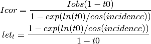
See reference on: J. Appl. Cryst. (2002). 35, 356–359 G. Wu et al. CCD phosphor
Parameters: - t0 – value of the normal transmission (from 0 to 1)
- shape – shape of the array
Returns: actual
- calcfrom1d(tth, I, shape=None, mask=None, dim1_unit=2th_deg, correctSolidAngle=True, dummy=0.0, polarization_factor=None, polarization_axis_offset=0, dark=None, flat=None)
Computes a 2D image from a 1D integrated profile
Parameters: - tth – 1D array with radial unit, this array needs to be ordered
- I – scattering intensity, corresponding intensity
- shape – shape of the image (if not defined by the detector)
- dim1_unit – unit for the “tth” array
- correctSolidAngle –
- dummy – value for masked pixels
- polarization_factor – set to true to use previously used value
- polarization_axis_offset – axis_offset to be send to the polarization method
- dark – dark current correction
- flat – flatfield corrction
Returns: 2D image reconstructed
- center_array(shape=None, unit='2th_deg', scale=True)
Generate a 2D array of the given shape with (i,j) (radial angle ) for all elements.
Parameters: - shape (2-tuple of integer) – expected shape
- unit – string like “2th_deg” or an instance of pyFAI.units.Unit
- scale – set to False for returning the internal representation (S.I. often) which is faster
Returns: 3d array with shape=(*shape,4,2) the two elements are: - dim3[0]: radial angle 2th, q, r... - dim3[1]: azimuthal angle chi
- chi(d1, d2, path='cython')
Calculate the chi (azimuthal angle) for the centre of a pixel at coordinate d1,d2 which in the lab ref has coordinate:
X1 = p1*cos(rot2)*cos(rot3) + p2*(cos(rot3)*sin(rot1)*sin(rot2) - cos(rot1)*sin(rot3)) - L*(cos(rot1)*cos(rot3)*sin(rot2) + sin(rot1)*sin(rot3)) X2 = p1*cos(rot2)*sin(rot3) - L*(-(cos(rot3)*sin(rot1)) + cos(rot1)*sin(rot2)*sin(rot3)) + p2*(cos(rot1)*cos(rot3) + sin(rot1)*sin(rot2)*sin(rot3)) X3 = -(L*cos(rot1)*cos(rot2)) + p2*cos(rot2)*sin(rot1) - p1*sin(rot2) hence tan(Chi) = X2 / X1
Parameters: - d1 (float or array of them) – pixel coordinate along the 1st dimention (C convention)
- d2 (float or array of them) – pixel coordinate along the 2nd dimention (C convention)
- path – can be “tan” (i.e via numpy) or “cython”
Returns: chi, the azimuthal angle in rad
- chiArray(shape=None)
Generate an array of azimuthal angle chi(i,j) for all elements in the detector.
Azimuthal angles are in radians
Nota: Refers to the pixel centers !
Parameters: shape – the shape of the chi array Returns: the chi array as numpy.ndarray
- chi_corner(d1, d2)
Calculate the chi (azimuthal angle) for the corner of a pixel at coordinate d1,d2 which in the lab ref has coordinate:
X1 = p1*cos(rot2)*cos(rot3) + p2*(cos(rot3)*sin(rot1)*sin(rot2) - cos(rot1)*sin(rot3)) - L*(cos(rot1)*cos(rot3)*sin(rot2) + sin(rot1)*sin(rot3)) X2 = p1*cos(rot2)*sin(rot3) - L*(-(cos(rot3)*sin(rot1)) + cos(rot1)*sin(rot2)*sin(rot3)) + p2*(cos(rot1)*cos(rot3) + sin(rot1)*sin(rot2)*sin(rot3)) X3 = -(L*cos(rot1)*cos(rot2)) + p2*cos(rot2)*sin(rot1) - p1*sin(rot2) hence tan(Chi) = X2 / X1
Parameters: - d1 (float or array of them) – pixel coordinate along the 1st dimention (C convention)
- d2 (float or array of them) – pixel coordinate along the 2nd dimention (C convention)
Returns: chi, the azimuthal angle in rad
- chia
chi array in cache
- cornerArray(*arg, **kw)
decorator that deprecates the use of a function
- cornerQArray(*arg, **kw)
decorator that deprecates the use of a function
- cornerRArray(*arg, **kw)
decorator that deprecates the use of a function
- cornerRd2Array(*arg, **kw)
decorator that deprecates the use of a function
- corner_array(shape=None, unit=None, use_cython=True, scale=True)
Generate a 3D array of the given shape with (i,j) (radial angle 2th, azimuthal angle chi ) for all elements.
Parameters: - shape (2-tuple of integer) – expected shape
- unit – string like “2th_deg” or an instance of pyFAI.units.Unit
- use_cython – set to False to use the slower Python path (for tests)
- scale – set to False for returning the internal representation (S.I. often) which is faster
Returns: 3d array with shape=(*shape,4,2) the two elements are: - dim3[0]: radial angle 2th, q, r... - dim3[1]: azimuthal angle chi
- correct_SA_spline
- cosIncidance(d1, d2, path='cython')
Calculate the incidence angle (alpha) for current pixels (P). The poni being the point of normal incidence, it’s incidence angle is ${alpha} = 0$ hence $cos({alpha}) = 1$
Parameters: - d1 – 1d or 2d set of points in pixel coord
- d2 – 1d or 2d set of points in pixel coord
Returns: cosine of the incidence angle
- del_chia()
- del_dssa()
- del_qa()
- del_ra()
- del_ttha()
- delta2Theta(shape=None)
Generate a 3D array of the given shape with (i,j) with the max distance between the center and any corner in 2 theta
Parameters: shape – The shape of the detector array: 2-tuple of integer Returns: 2D-array containing the max delta angle between a pixel center and any corner in 2theta-angle (rad)
- deltaChi(shape=None, use_cython=True)
Generate a 3D array of the given shape with (i,j) with the max distance between the center and any corner in chi-angle (rad)
Parameters: shape – The shape of the detector array: 2-tuple of integer Returns: 2D-array containing the max delta angle between a pixel center and any corner in chi-angle (rad)
- deltaQ(shape=None)
Generate a 2D array of the given shape with (i,j) with the max distance between the center and any corner in q_vector unit (nm^-1)
Parameters: shape – The shape of the detector array: 2-tuple of integer Returns: array 2D containing the max delta Q between a pixel center and any corner in q_vector unit (nm^-1)
- deltaR(shape=None)
Generate a 2D array of the given shape with (i,j) with the max distance between the center and any corner in radius unit (mm)
Parameters: shape – The shape of the detector array: 2-tuple of integer Returns: array 2D containing the max delta Q between a pixel center and any corner in q_vector unit (nm^-1)
- deltaRd2(shape=None)
Generate a 2D array of the given shape with (i,j) with the max distance between the center and any corner in unit: reciprocal spacing squarred (1/nm^2)
Parameters: shape – The shape of the detector array: 2-tuple of integer Returns: array 2D containing the max delta (d*)^2 between a pixel center and any corner in reciprocal spacing squarred (1/nm^2)
- delta_array(shape=None, unit='2th_deg', scale=False)
Generate a 2D array of the given shape with (i,j) (delta-radial angle) for all elements.
Parameters: - shape (2-tuple of integer) – expected shape
- unit – string like “2th_deg” or an instance of pyFAI.units.Unit
- scale – set to False for returning the internal representation (S.I. often) which is faster
Returns: 3d array with shape=(*shape,4,2) the two elements are:
- dim3[0]: radial angle 2th, q, r...
- dim3[1]: azimuthal angle chi
- diffSolidAngle(d1, d2)
Calculate the solid angle of the current pixels (P) versus the PONI (C)
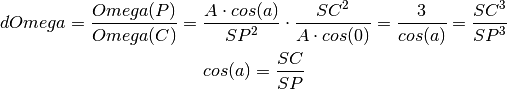
Parameters: - d1 – 1d or 2d set of points
- d2 – 1d or 2d set of points (same size&shape as d1)
Returns: solid angle correction array
- dist
- dssa
solid angle array in cache
- getFit2D()
Export geometry setup with the geometry of Fit2D
Returns: dict with parameters compatible with fit2D geometry
- getPyFAI()
Export geometry setup with the geometry of PyFAI
Returns: dict with the parameter-set of the PyFAI geometry
- getSPD()
get the SPD like parameter set: For geometry description see Peter Boesecke J.Appl.Cryst.(2007).40, s423–s427
Basically the main difference with pyFAI is the order of the axis which are flipped
Returns: dictionnary with those parameters: SampleDistance: distance from sample to detector at the PONI (orthogonal projection) Center_1, pixel position of the PONI along fastest axis Center_2: pixel position of the PONI along slowest axis Rot_1: rotation around the fastest axis (x) Rot_2: rotation around the slowest axis (y) Rot_3: rotation around the axis ORTHOGONAL to the detector plan PSize_1: pixel size in meter along the fastest dimention PSize_2: pixel size in meter along the slowst dimention splineFile: name of the file containing the spline BSize_1: pixel binning factor along the fastest dimention BSize_2: pixel binning factor along the slowst dimention WaveLength: wavelength used in meter
- get_chia()
- get_correct_solid_angle_for_spline()
- get_dist()
- get_dssa()
- get_mask()
- get_maskfile()
- get_pixel1()
- get_pixel2()
- get_poni1()
- get_poni2()
- get_qa()
- get_ra()
- get_rot1()
- get_rot2()
- get_rot3()
- get_shape(shape=None)
Guess what is the best shape ....
Parameters: shape – force this value (2-tuple of int) Returns: 2-tuple of int
- get_spline()
- get_splineFile()
- get_ttha()
- get_wavelength()
- load(filename)
Load the refined parameters from a file.
Parameters: filename (string) – name of the file to load
- make_headers(type_='list')
Create a configuration for the
Parameters: type – can be “list” or “dict” Returns: the header with the proper format
- mask
- maskfile
- oversampleArray(myarray)
- pixel1
- pixel2
- polarization(shape=None, factor=None, axis_offset=0, with_checksum=False)
Calculate the polarization correction accoding to the polarization factor:
- If the polarization factor is None,
the correction is not applied (returns 1)
- If the polarization factor is 0 (circular polarization),
the correction correspond to (1+(cos2θ)^2)/2
- If the polarization factor is 1 (linear horizontal polarization),
there is no correction in the vertical plane and a node at 2th=90, chi=0
- If the polarization factor is -1 (linear vertical polarization),
there is no correction in the horizontal plane and a node at 2th=90, chi=90
If the polarization is elliptical, the polarization factor varies between -1 and +1.
The axis_offset parameter allows correction for the misalignement of the polarization plane (or ellipse main axis) and the the detector’s X axis.
Parameters: - factor – (Ih-Iv)/(Ih+Iv): varies between 0 (circular/random polarization) and 1 (where division by 0 could occure at 2th=90, chi=0)
- axis_offset – Angle between the polarization main axis and detector’s X direction (in radians !!!)
Returns: 2D array with polarization correction array (intensity/polarisation)
- poni1
- poni2
- positionArray(*arg, **kw)
decorator that deprecates the use of a function
- position_array(shape=None, corners=False, dtype=<type 'numpy.float64'>, use_cython=True)
Generate an array for the pixel position given the shape of the detector.
if corners is False, the coordinates of the center of the pixel is returned in an array of shape: (shape[0], shape[1], 3) where the 3 coordinates are: * z: along incident beam, * y: to the top/sky, * x: towards the center of the ring
If is True, the corner of each pixels are then returned. the output shape is then (shape[0], shape[1], 4, 3)
Parameters: - shape – shape of the array expected
- corners – set to true to receive a (...,4,3) array of corner positions
- dtype – output format requested. Double precision is needed for fitting the geometry
- use_cython ((bool)) – set to false to test the Python path (slower)
Returns: 3D coodinates as nd-array of size (...,3) or (...,3) (default)
Nota: this value is not cached and actually generated on demand (costly)
- qArray(shape=None)
Generate an array of the given shape with q(i,j) for all elements.
- qCornerFunct(*arg, **kw)
decorator that deprecates the use of a function
- qFunction(d1, d2, param=None, path='cython')
Calculates the q value for the center of a given pixel (or set of pixels) in nm-1
q = 4pi/lambda sin( 2theta / 2 )
Parameters: - d1 (scalar or array of scalar) – position(s) in pixel in first dimension (c order)
- d2 (scalar or array of scalar) – position(s) in pixel in second dimension (c order)
Returns: q in in nm^(-1)
Return type: float or array of floats.
- qa
Q array in cache
- rArray(shape=None)
Generate an array of the given shape with r(i,j) for all elements; The radius r being in meters.
Parameters: shape – expected shape of the detector Returns: 2d array of the given shape with radius in m from beam center on detector.
- rCornerFunct(*arg, **kw)
decorator that deprecates the use of a function
- rFunction(d1, d2, param=None, path='cython')
Calculates the radius value for the center of a given pixel (or set of pixels) in m
r = distance to the incident beamParameters: - d1 (scalar or array of scalar) – position(s) in pixel in first dimension (c order)
- d2 (scalar or array of scalar) – position(s) in pixel in second dimension (c order)
Returns: r in in m
Return type: float or array of floats.
- ra
R array in cache
- rd2Array(shape=None)
Generate an array of the given shape with (d*(i,j))^2 for all pixels.
d*^2 is the reciprocal spacing squared in inverse nm squared
Parameters: shape – expected shape of the detector Returns: 2d array of the given shape with reciprocal spacing squared
- read(filename)
Load the refined parameters from a file.
Parameters: filename (string) – name of the file to load
- reset()
reset most arrays that are cached: used when a parameter changes.
- rot1
- rot2
- rot3
- save(filename)
Save the geometry parameters.
Parameters: filename (string) – name of the file where to save the parameters
- setChiDiscAtPi()
Set the position of the discontinuity of the chi axis between -pi and +pi. This is the default behavour
- setChiDiscAtZero()
Set the position of the discontinuity of the chi axis between 0 and 2pi. By default it is between pi and -pi
- setFit2D(directDist, centerX, centerY, tilt=0.0, tiltPlanRotation=0.0, pixelX=None, pixelY=None, splineFile=None)
Set the Fit2D-like parameter set: For geometry description see HPR 1996 (14) pp-240
Warning: Fit2D flips automatically images depending on their file-format. By reverse engineering we noticed this behavour for Tiff and Mar345 images (at least). To obtaine correct result you will have to flip images using numpy.flipud.
Parameters: - direct – direct distance from sample to detector along the incident beam (in millimeter as in fit2d)
- tilt – tilt in degrees
- tiltPlanRotation – Rotation (in degrees) of the tilt plan arround the Z-detector axis * 0deg -> Y does not move, +X goes to Z<0 * 90deg -> X does not move, +Y goes to Z<0 * 180deg -> Y does not move, +X goes to Z>0 * 270deg -> X does not move, +Y goes to Z>0
- pixelX,pixelY – as in fit2d they ar given in micron, not in meter
- centerY (centerX,) – pixel position of the beam center
- splineFile – name of the file containing the spline
- setOversampling(*arg, **kw)
decorator that deprecates the use of a function
- setPyFAI(**kwargs)
set the geometry from a pyFAI-like dict
- setSPD(SampleDistance, Center_1, Center_2, Rot_1=0, Rot_2=0, Rot_3=0, PSize_1=None, PSize_2=None, splineFile=None, BSize_1=1, BSize_2=1, WaveLength=None)
Set the SPD like parameter set: For geometry description see Peter Boesecke J.Appl.Cryst.(2007).40, s423–s427
Basically the main difference with pyFAI is the order of the axis which are flipped
Parameters: - SampleDistance – distance from sample to detector at the PONI (orthogonal projection)
- Center_1 – pixel position of the PONI along fastest axis
- Center_2 – pixel position of the PONI along slowest axis
- Rot_1 – rotation around the fastest axis (x)
- Rot_2 – rotation around the slowest axis (y)
- Rot_3 – rotation around the axis ORTHOGONAL to the detector plan
- PSize_1 – pixel size in meter along the fastest dimention
- PSize_2 – pixel size in meter along the slowst dimention
- splineFile – name of the file containing the spline
- BSize_1 – pixel binning factor along the fastest dimention
- BSize_2 – pixel binning factor along the slowst dimention
- WaveLength – wavelength used
- set_chia(_)
- set_correct_solid_angle_for_spline(value)
- set_dist(value)
- set_dssa(_)
- set_mask(mask)
- set_maskfile(maskfile)
- set_param(param)
set the geometry from a 6-tuple with dist, poni1, poni2, rot1, rot2, rot3
- set_pixel1(pixel1)
- set_pixel2(pixel2)
- set_poni1(value)
- set_poni2(value)
- set_qa(_)
- set_ra(_)
- set_rot1(value)
- set_rot2(value)
- set_rot3(value)
- set_spline(spline)
- set_splineFile(splineFile)
- set_ttha(_)
- set_wavelength(value)
- classmethod sload(filename)
A static method combining the constructor and the loader from a file
Parameters: filename (string) – name of the file to load Returns: instance of Gerometry of AzimuthalIntegrator set-up with the parameter from the file.
- solidAngleArray(shape=None, order=3, absolute=False)
Generate an array for the solid angle correction given the shape of the detector.
solid_angle = cos(incidence)^3
Parameters: - shape – shape of the array expected
- order – should be 3, power of the formula just obove
- absolute – the absolute solid angle is calculated as:
SA = pix1*pix2/dist^2 * cos(incidence)^3
- spline
- splineFile
- tth(d1, d2, param=None, path='cython')
Calculates the 2theta value for the center of a given pixel (or set of pixels)
Parameters: - d1 (scalar or array of scalar) – position(s) in pixel in first dimension (c order)
- d2 (scalar or array of scalar) – position(s) in pixel in second dimension (c order)
- path – can be “cos”, “tan” or “cython”
Returns: 2theta in radians
Return type: float or array of floats.
- tth_corner(*arg, **kw)
decorator that deprecates the use of a function
- ttha
2theta array in cache
- twoThetaArray(shape=None)
Generate an array of two-theta(i,j) in radians for each pixel in detector
the 2theta array values are in radians
Parameters: shape – shape of the detector Returns: array of 2theta position in radians
- wavelength
- write(filename)
Save the geometry parameters.
Parameters: filename (string) – name of the file where to save the parameters
geometryRefinement Module
Module used to perform the geometric refinement of the model
- class pyFAI.geometryRefinement.GeometryRefinement(data=None, dist=1, poni1=None, poni2=None, rot1=0, rot2=0, rot3=0, pixel1=None, pixel2=None, splineFile=None, detector=None, wavelength=None, calibrant=None)
Bases: pyFAI.azimuthalIntegrator.AzimuthalIntegrator
- __init__(data=None, dist=1, poni1=None, poni2=None, rot1=0, rot2=0, rot3=0, pixel1=None, pixel2=None, splineFile=None, detector=None, wavelength=None, calibrant=None)
Parameters: - data – ndarray float64 shape = n, 3 col0: pos in dim0 (in pixels) col1: pos in dim1 (in pixels) col2: ring index in calibrant object
- dist – guessed sample-detector distance (optional, in m)
- poni1 – guessed PONI coordinate along the Y axis (optional, in m)
- poni2 – guessed PONI coordinate along the X axis (optional, in m)
- rot1 – guessed tilt of the detector around the Y axis (optional, in rad)
- rot2 – guessed tilt of the detector around the X axis (optional, in rad)
- rot3 – guessed tilt of the detector around the incoming beam axis (optional, in rad)
- pixel1 – Pixel size along the vertical direction of the detector (in m), almost mandatory
- pixel2 – Pixel size along the horizontal direction of the detector (in m), almost mandatory
- splineFile – file describing the detector as 2 cubic splines. Replaces pixel1 & pixel2
- detector – name of the detector or Detector instance. Replaces splineFile, pixel1 & pixel2
- wavelength – wavelength in m (1.54e-10)
- calibrant – instance of pyFAI.calibrant.Calibrant containing the d-Spacing
- anneal(maxiter=1000000)
- calc_2th(rings, wavelength=None)
Parameters: - rings – indices of the rings. starts at 0 and self.dSpacing should be long enough !!!
- wavelength – wavelength in meter
- chi2(param=None)
- chi2_wavelength(param=None)
- confidence(with_rot=True)
Confidence interval obtained from the second derivative of the error function next to its minimum value.
Note the confidence interval increases with the number of points which is “surprizing”
Parameters: with_rot – if true include rot1 & rot2 in the parameter set. Returns: std_dev, confidence
- curve_fit(with_rot=True)
Refine the geometry and provide confidence interval Use curve_fit from scipy.optimize to not only refine the geometry (unconstrained fit)
Parameters: with_rot – include rotation intro error measurment Returns: std_dev, confidence
- dist_max
- dist_min
- get_dist_max()
- get_dist_min()
- get_poni1_max()
- get_poni1_min()
- get_poni2_max()
- get_poni2_min()
- get_rot1_max()
- get_rot1_min()
- get_rot2_max()
- get_rot2_min()
- get_rot3_max()
- get_rot3_min()
- get_wavelength_max()
- get_wavelength_min()
- guess_poni()
PONI can be guessed by the centroid of the ring with lowest 2Theta
It may try to fit an ellipse and sometimes it works
- poni1_max
- poni1_min
- poni2_max
- poni2_min
- refine1()
- refine2(maxiter=1000000, fix=None)
- refine2_wavelength(maxiter=1000000, fix=None)
- residu1(param, d1, d2, rings)
- residu1_wavelength(param, d1, d2, rings)
- residu2(param, d1, d2, rings)
- residu2_wavelength(param, d1, d2, rings)
- residu2_wavelength_weighted(param, d1, d2, rings, weight)
- residu2_weighted(param, d1, d2, rings, weight)
- roca()
run roca to optimise the parameter set
- rot1_max
- rot1_min
- rot2_max
- rot2_min
- rot3_max
- rot3_min
- set_dist_max(value)
- set_dist_min(value)
- set_poni1_max(value)
- set_poni1_min(value)
- set_poni2_max(value)
- set_poni2_min(value)
- set_rot1_max(value)
- set_rot1_min(value)
- set_rot2_max(value)
- set_rot2_min(value)
- set_rot3_max(value)
- set_rot3_min(value)
- set_tolerance(value=10)
Set the tolerance for a refinement of the geometry; in percent of the original value
Parameters: value – Tolerance as a percentage
- set_wavelength_max(value)
- set_wavelength_min(value)
- simplex(maxiter=1000000)
- wavelength_max
- wavelength_min
goniometer Module
Everything you need to calibrate a detector mounted on a goniometer or any translation table
- class pyFAI.goniometer.GeometryTransformation(dist_expr, poni1_expr, poni2_expr, rot1_expr, rot2_expr, rot3_expr, param_names, pos_names=None, constants=None, content=None)
Bases: object
This class, once instanciated, behaves like a function (via the __call__ method). It is responsible for taking any input geometry and translate it into a set of parameters compatible with pyFAI, i.e. a tuple with: (dist, poni1, poni2, rot1, rot2, rot3)
This function uses numexpr for formula evaluation.
- __init__(dist_expr, poni1_expr, poni2_expr, rot1_expr, rot2_expr, rot3_expr, param_names, pos_names=None, constants=None, content=None)
Constructor of the class
Parameters: - dist_expr – formula (as string) providing with the dist
- poni1_expr – formula (as string) providing with the poni1
- poni2_expr – formula (as string) providing with the poni2
- rot1_expr – formula (as string) providing with the rot1
- rot2_expr – formula (as string) providing with the rot2
- rot3_expr – formula (as string) providing with the rot3
- param_names – list of names of the parameters used in the model
- pos_names – list of motor names for gonio with >1 degree of freedom
- constants – a dictionary with some constants the user may want to use
- content – Should be None or the name of the class (may be used in the future to dispatch to multiple derivative classes)
- to_dict()
Export the instance representation for serialization as a dictionary
- pyFAI.goniometer.GeometryTranslation
alias of GeometryTransformation
- class pyFAI.goniometer.Goniometer(param, trans_function, detector='Detector', wavelength=None, param_names=None, pos_names=None)
Bases: object
This class represents the goniometer model. Unlike this name suggests, it may include translation in addition to rotations
- __init__(param, trans_function, detector='Detector', wavelength=None, param_names=None, pos_names=None)
Constructor of the Goniometer class.
Parameters: - param – vector of parameter to refine for defining the detector position on the goniometer
- trans_function – function taking the parameters of the goniometer and the goniometer position and return the 6 parameters [dist, poni1, poni2, rot1, rot2, rot3]
- detector – detector mounted on the moving arm
- wavelength – the wavelength used for the experiment
- param_names – list of names to “label” the param vector.
- pos_names – list of names to “label” the position vector of the gonio.
- file_version = 'Goniometer calibration v1.0'
- get_ai(position)
Creates an azimuthal integrator from the motor position
Parameters: position – the goniometer position, a float for a 1 axis goniometer Returns: A freshly build AzimuthalIntegrator
- get_mg(positions)
Creates a MultiGeometry integrator from a list of goniometer positions.
Parameters: positions – A list of goniometer positions Returns: A freshly build multi-geometry
- save(filename)
Save the goniometer configuration to file
Parameters: filename – name of the file to save configuration to
- classmethod sload(filename)
- to_dict()
Export the goniometer configuration to a dictionary
Returns: Ordered dictionary
- write(filename)
Save the goniometer configuration to file
Parameters: filename – name of the file to save configuration to
- class pyFAI.goniometer.GoniometerRefinement(param, pos_function, trans_function, detector='Detector', wavelength=None, param_names=None, pos_names=None, bounds=None)
Bases: pyFAI.goniometer.Goniometer
This class allow the translation of a goniometer geometry into a pyFAI geometry using a set of parameter to refine.
- __init__(param, pos_function, trans_function, detector='Detector', wavelength=None, param_names=None, pos_names=None, bounds=None)
Constructor of the GoniometerRefinement class
Parameters: - param – vector of parameter to refine for defining the detector position on the goniometer
- pos_function – a function taking metadata and extracting the goniometer position
- trans_function – function taking the parameters of the goniometer and the gonopmeter position and return the 6 parameters [dist, poni1, poni2, rot1, rot2, rot3]
- detector – detector mounted on the moving arm
- wavelength – the wavelength used for the experiment
- param_names – list of names to “label” the param vector.
- pos_names – list of names to “label” the position vector of the gonio.
- bounds – list of 2-tuple with the lower and upper bound of each function
- chi2(param=None)
Calculate the average of the square of the error for a given parameter set
- new_geometry(label, image=None, metadata=None, control_points=None, calibrant=None, geometry=None)
Add a new geometry for calibration
Parameters: - label – usually a string
- image – 2D numpy array with the Debye scherrer rings
- metadata – some metadata
- control_points – an instance of ControlPoints
- calibrant – the calibrant used for calibrating
- geometry – poni or AzimuthalIntegrator instance.
- refine2(method='slsqp', **options)
Geometry refinement tool
See https://docs.scipy.org/doc/scipy-0.18.1/reference/generated/scipy.optimize.minimize.html
Parameters: - method – name of the minimizer
- options – options for the minimizer
- residu2(param)
Actually performs the calulation of the average of the error squared
- set_bounds(name, mini=None, maxi=None)
Redefines the bounds for the refinement
Parameters: - name – name of the parameter or index in the parameter set
- mini – minimum value
- maxi – maximum value
- class pyFAI.goniometer.PoniParam
Bases: tuple
PoniParam(dist, poni1, poni2, rot1, rot2, rot3)
- dist
Alias for field number 0
- poni1
Alias for field number 1
- poni2
Alias for field number 2
- rot1
Alias for field number 3
- rot2
Alias for field number 4
- rot3
Alias for field number 5
- class pyFAI.goniometer.SingleGeometry(label, image=None, metadata=None, pos_function=None, control_points=None, calibrant=None, detector=None, geometry=None)
Bases: object
This class represents a single geometry of a detector position on a goniometer arm
- __init__(label, image=None, metadata=None, pos_function=None, control_points=None, calibrant=None, detector=None, geometry=None)
Constructor of the SingleGeometry class, used for calibrating a multi-geometry setup with a moving detector.
Parameters: - label – name of the geometry, a string or anything unmutable
- image – image with Debye-Scherrer rings as 2d numpy array
- metadata – anything which contains the goniometer position
- pos_function – a function which takes the metadata as input and returns the goniometer arm position
- control_points – a pyFAI.control_points.ControlPoints instance (optional parameter)
- calibrant – a pyFAI.calibrant.Calibrant instance. Contains the wavelength to be used (optional parameter)
- detector – a pyFAI.detectors.Detector instance or something like that Contains the mask to be used (optional parameter)
- geometry – an azimuthal integrator or a ponifile (or a dict with the geometry) (optional parameter)
- extract_cp(max_rings=None, pts_per_deg=1.0)
Performs an automatic keypoint extraction and update the geometry refinement part
Parameters: - max_ring – extract at most N rings from the image
- pts_per_deg – number of control points per azimuthal degree (increase for better precision)
- get_ai()
Create a new azimuthal integrator to be used.
Returns: Azimuthal Integrator instance
- get_position()
This method is in charge of calculating the motor position from metadata/label/...
detectors Module
Description of all detectors with a factory to instantiate them
- class pyFAI.detectors.ADSC_Q210(pixel1=5.1e-05, pixel2=5.1e-05)
Bases: pyFAI.detectors.Detector
ADSC Quantum 210r detector, 2x2 chips
Informations from http://www.adsc-xray.com/products/ccd-detectors/q210r-ccd-detector/
Question: how are the gaps handled ?
- MAX_SHAPE = (4096, 4096)
- __init__(pixel1=5.1e-05, pixel2=5.1e-05)
- aliases = ['Quantum 210']
- force_pixel = True
- class pyFAI.detectors.ADSC_Q270(pixel1=6.48e-05, pixel2=6.48e-05)
Bases: pyFAI.detectors.Detector
ADSC Quantum 270r detector, 2x2 chips
Informations from http://www.adsc-xray.com/products/ccd-detectors/q270-ccd-detector/
Question: how are the gaps handled ?
- MAX_SHAPE = (4168, 4168)
- __init__(pixel1=6.48e-05, pixel2=6.48e-05)
- aliases = ['Quantum 270']
- force_pixel = True
- class pyFAI.detectors.ADSC_Q315(pixel1=5.1e-05, pixel2=5.1e-05)
Bases: pyFAI.detectors.Detector
ADSC Quantum 315r detector, 3x3 chips
Informations from http://www.adsc-xray.com/products/ccd-detectors/q315r-ccd-detector/
Question: how are the gaps handled ?
- MAX_SHAPE = (6144, 6144)
- __init__(pixel1=5.1e-05, pixel2=5.1e-05)
- aliases = ['Quantum 315']
- force_pixel = True
- class pyFAI.detectors.ADSC_Q4(pixel1=8.2e-05, pixel2=8.2e-05)
Bases: pyFAI.detectors.Detector
ADSC Quantum 4r detector, 2x2 chips
Informations from http://proteincrystallography.org/detectors/adsc.php
Question: how are the gaps handled ?
- MAX_SHAPE = (2304, 2304)
- __init__(pixel1=8.2e-05, pixel2=8.2e-05)
- aliases = ['Quantum 4']
- force_pixel = True
- class pyFAI.detectors.Aarhus(pixel1=2.5e-05, pixel2=2.5e-05, radius=0.3)
Bases: pyFAI.detectors.Detector
Cylindrical detector made of a bent imaging-plate. Developped at the Danish university of Aarhus r = 1.2m or 0.3m
The image has to be laid-out horizontally
Nota: the detector is bending towards the sample, hence reducing the sample-detector distance. This is why z<0 (or p3<0)
TODO: update cython code for 3d detectors use expand2d instead of outer product with ones
- IS_FLAT = False
- MAX_SHAPE = (1000, 16000)
- __init__(pixel1=2.5e-05, pixel2=2.5e-05, radius=0.3)
- calc_cartesian_positions(d1=None, d2=None, center=True, use_cython=True)
Calculate the position of each pixel center in cartesian coordinate and in meter of a couple of coordinates. The half pixel offset is taken into account here !!! Adapted to Nexus detector definition
Parameters: - d1 (ndarray (1D or 2D)) – the Y pixel positions (slow dimension)
- d2 (ndarray (1D or 2D)) – the X pixel positions (fast dimension)
- center – retrieve the coordinate of the center of the pixel
- use_cython – set to False to test Python implementeation
Returns: position in meter of the center of each pixels.
Return type: ndarray
d1 and d2 must have the same shape, returned array will have the same shape.
- force_pixel = True
- get_pixel_corners(use_cython=True)
Calculate the position of the corner of the pixels
This should be overwritten by class representing non-contiguous detector (Xpad, ...)
Returns: 4D array containing: pixel index (slow dimension) pixel index (fast dimension) corner index (A, B, C or D), triangles or hexagons can be handled the same way vertex position (z,y,x)
- class pyFAI.detectors.Apex2(pixel1=0.00012, pixel2=0.00012)
Bases: pyFAI.detectors.Detector
BrukerApex2 detector
Actually a derivative from the Fairchild detector with higher binning
- DEFAULT_PIXEL1 = 6e-05
- DEFAULT_PIXEL2 = 6e-05
- MAX_SHAPE = (1024, 1024)
- __init__(pixel1=0.00012, pixel2=0.00012)
Defaults to 2x2 binning
- aliases = ['ApexII', 'Bruker']
- force_pixel = True
- class pyFAI.detectors.Basler(pixel=3.75e-06)
Bases: pyFAI.detectors.Detector
Basler camera are simple CCD camara over GigaE
- MAX_SHAPE = (966, 1296)
- __init__(pixel=3.75e-06)
- aliases = ['aca1300']
- force_pixel = True
- class pyFAI.detectors.Detector(pixel1=None, pixel2=None, splineFile=None, max_shape=None)
Bases: object
Generic class representing a 2D detector
- API_VERSION = '1.0'
- HAVE_TAPER = False
If true a spline file is mandatory to correct the geometry
- IS_CONTIGUOUS = True
- IS_FLAT = True
- __init__(pixel1=None, pixel2=None, splineFile=None, max_shape=None)
Parameters: - pixel1 (float) – size of the pixel in meter along the slow dimension (often Y)
- pixel2 (float) – size of the pixel in meter along the fast dimension (often X)
- splineFile (str) – path to file containing the geometric correction.
- max_shape (2-tuple of integrers) – maximum size of the detector
- aliases = []
- binning
- calc_cartesian_positions(d1=None, d2=None, center=True, use_cython=True)
Calculate the position of each pixel center in cartesian coordinate and in meter of a couple of coordinates. The half pixel offset is taken into account here !!! Adapted to Nexus detector definition
Parameters: - d1 (ndarray (1D or 2D)) – the Y pixel positions (slow dimension)
- d2 (ndarray (1D or 2D)) – the X pixel positions (fast dimension)
- center – retrieve the coordinate of the center of the pixel, unless gives one corner
- use_cython – set to False to test Python implementation
Returns: position in meter of the center of each pixels.
Return type: 3xndarray, the later being None if IS_FLAT
d1 and d2 must have the same shape, returned array will have the same shape.
pos_z is None for flat detectors
- calc_mask()
Method calculating the mask for a given detector
Detectors with gaps should overwrite this method with something actually calculating the mask!
Returns: the mask with valid pixel to 0 Return type: numpy ndarray of int8 or None
- darkcurrent
- classmethod factory(name, config=None)
A kind of factory...
Parameters: - name (str) – name of a detector
- config (dict or JSON representation of it.) – configuration of the detector
Returns: an instance of the right detector, set-up if possible
Return type: pyFAI.detectors.Detector
- flatfield
- force_pixel = False
- classmethod from_dict(dico)
Creates a brand new detector from the description of the detector as a dict
Parameters: dico – JSON serializable dictionary Returns: Detector instance
- getFit2D()
Helper method to serialize the description of a detector using the Fit2d units
Returns: representation of the detector easy to serialize Return type: dict
- getPyFAI()
Helper method to serialize the description of a detector using the pyFAI way with everything in S.I units.
Returns: representation of the detector easy to serialize Return type: dict
- get_binning()
- get_darkcurrent()
- get_darkcurrent_crc()
- get_flatfield()
- get_flatfield_crc()
- get_mask()
- get_mask_crc()
- get_maskfile()
- get_name()
Get a meaningful name for detector
- get_pixel1()
- get_pixel2()
- get_pixel_corners()
Calculate the position of the corner of the pixels
This should be overwritten by class representing non-contiguous detector (Xpad, ...)
Precision float32 is ok: precision of 1µm for a detector size of 1m
Returns: 4D array containing: pixel index (slow dimension) pixel index (fast dimension) corner index (A, B, C or D), triangles or hexagons can be handled the same way vertex position (z,y,x)
- get_splineFile()
- guess_binning(data)
Guess the binning/mode depending on the image shape :param data: 2-tuple with the shape of the image or the image with a .shape attribute.
- mask
- maskfile
- name
Get a meaningful name for detector
- pixel1
- pixel2
- registry = {'pilatus1m_cdte': <class 'pyFAI.detectors.PilatusCdTe1M'>, 'imxpads10': <class 'pyFAI.detectors.ImXPadS10'>, 'pilatus1mcdte': <class 'pyFAI.detectors.PilatusCdTe1M'>, 'rayonix_mx225hs': <class 'pyFAI.detectors.RayonixMx225hs'>, 'pilatus_cdte_2m': <class 'pyFAI.detectors.PilatusCdTe2M'>, 'd5': <class 'pyFAI.detectors.Xpad_flat'>, 'eiger_500k': <class 'pyFAI.detectors.Eiger500k'>, 'rayonix_mx170-hs': <class 'pyFAI.detectors.RayonixMx170'>, 'imxpad_s10': <class 'pyFAI.detectors.ImXPadS10'>, 'rayonix_mx340hs': <class 'pyFAI.detectors.RayonixMx340hs'>, 'condor': <class 'pyFAI.detectors.Fairchild'>, 'eiger16m': <class 'pyFAI.detectors.Eiger16M'>, 'pilatus_1m': <class 'pyFAI.detectors.Pilatus1M'>, 'oxd_titan': <class 'pyFAI.detectors.Titan'>, 'perkin_detector': <class 'pyFAI.detectors.Perkin'>, 'pilatus6m': <class 'pyFAI.detectors.Pilatus6M'>, 'titan_2k_x_2k': <class 'pyFAI.detectors.Titan'>, 'hf_262k': <class 'pyFAI.detectors.HF_262k'>, 'thales_electronics': <class 'pyFAI.detectors.Pixium'>, 'rayonixlx255': <class 'pyFAI.detectors.RayonixLx255'>, 'rayonixsx200': <class 'pyFAI.detectors.RayonixSx200'>, 'eiger4m': <class 'pyFAI.detectors.Eiger4M'>, 'rayonix_lx170': <class 'pyFAI.detectors.RayonixLx170'>, 'pilatuscdte300kw': <class 'pyFAI.detectors.PilatusCdTe300kw'>, 'pilatus300k': <class 'pyFAI.detectors.Pilatus300k'>, 'picamv2': <class 'pyFAI.detectors.RaspberryPi8M'>, 'picamv1': <class 'pyFAI.detectors.RaspberryPi5M'>, 'quantum_270': <class 'pyFAI.detectors.ADSC_Q270'>, 'rayonixmx300': <class 'pyFAI.detectors.RayonixMx300'>, 'pilatus300kw_cdte': <class 'pyFAI.detectors.PilatusCdTe300kw'>, 'rayonixlx225hs': <class 'pyFAI.detectors.RayonixLx255'>, 'pilatuscdte1m': <class 'pyFAI.detectors.PilatusCdTe1M'>, 'raspberrypi5m': <class 'pyFAI.detectors.RaspberryPi5M'>, 'pilatus_cdte_300kw': <class 'pyFAI.detectors.PilatusCdTe300kw'>, 'perkin': <class 'pyFAI.detectors.Perkin'>, 'rayonixmx340hs': <class 'pyFAI.detectors.RayonixMx340hs'>, 'rayonix_mx325': <class 'pyFAI.detectors.RayonixMx325'>, 'picam_v2': <class 'pyFAI.detectors.RaspberryPi8M'>, 'adsc_q270': <class 'pyFAI.detectors.ADSC_Q270'>, 'rayonixmx170hs': <class 'pyFAI.detectors.RayonixMx170'>, 'pilatus_6m': <class 'pyFAI.detectors.Pilatus6M'>, 'oxdtitan': <class 'pyFAI.detectors.Titan'>, 'dexela2923': <class 'pyFAI.detectors.Dexela2923'>, 'xpads540flat': <class 'pyFAI.detectors.Xpad_flat'>, 'titan': <class 'pyFAI.detectors.Titan'>, 'aarhus': <class 'pyFAI.detectors.Aarhus'>, 'rayonix_mx425hs': <class 'pyFAI.detectors.RayonixMx425hs'>, 'hf_4m': <class 'pyFAI.detectors.HF_4M'>, 'pilatuscdte2m': <class 'pyFAI.detectors.PilatusCdTe2M'>, 'pilatuscdte300k': <class 'pyFAI.detectors.PilatusCdTe300k'>, 'pilatus_1m_cdte': <class 'pyFAI.detectors.PilatusCdTe1M'>, 'pilatus_300kw': <class 'pyFAI.detectors.Pilatus300kw'>, 'rayonixmx170-hs': <class 'pyFAI.detectors.RayonixMx170'>, 'rayonixmx300hs': <class 'pyFAI.detectors.RayonixMx300hs'>, 'pixium4700detector': <class 'pyFAI.detectors.Pixium'>, 'rayonixlx255-hs': <class 'pyFAI.detectors.RayonixLx255'>, 'agilenttitan': <class 'pyFAI.detectors.Titan'>, 'eiger500k': <class 'pyFAI.detectors.Eiger500k'>, 'rayonixsx165': <class 'pyFAI.detectors.RayonixSx165'>, 'pilatus100k': <class 'pyFAI.detectors.Pilatus100k'>, 'rayonix_lx170-hs': <class 'pyFAI.detectors.RayonixLx170'>, 'perkin_elmer': <class 'pyFAI.detectors.Perkin'>, 'aca1300': <class 'pyFAI.detectors.Basler'>, 'quantum315': <class 'pyFAI.detectors.ADSC_Q315'>, 'quantum4': <class 'pyFAI.detectors.ADSC_Q4'>, 'rayonixsx85hs': <class 'pyFAI.detectors.RayonixSx85hs'>, 'eiger_4m': <class 'pyFAI.detectors.Eiger4M'>, 'imxpads140': <class 'pyFAI.detectors.ImXPadS140'>, 'rayonix_mx170': <class 'pyFAI.detectors.RayonixMx170'>, 'pilatus300kw': <class 'pyFAI.detectors.Pilatus300kw'>, 'hf-130k': <class 'pyFAI.detectors.HF_130K'>, 'pilatus_100k': <class 'pyFAI.detectors.Pilatus100k'>, 'rayonixsx30hs': <class 'pyFAI.detectors.RayonixSx30hs'>, 'mar345': <class 'pyFAI.detectors.Mar345'>, 'perkindetector': <class 'pyFAI.detectors.Perkin'>, 'rayonix_mx425_hs': <class 'pyFAI.detectors.RayonixMx425hs'>, 'rayonix_mx225': <class 'pyFAI.detectors.RayonixMx225'>, 'eiger1m': <class 'pyFAI.detectors.Eiger1M'>, 'mar_345': <class 'pyFAI.detectors.Mar345'>, 'pilatus2m': <class 'pyFAI.detectors.Pilatus2M'>, 'hf_9m': <class 'pyFAI.detectors.HF_9M'>, 'rayonixlx170hs': <class 'pyFAI.detectors.RayonixLx170'>, 'hf-1m': <class 'pyFAI.detectors.HF_1M'>, 'eiger_1m': <class 'pyFAI.detectors.Eiger1M'>, 'rayonix_lx170_hs': <class 'pyFAI.detectors.RayonixLx170'>, 'rayonixmx170': <class 'pyFAI.detectors.RayonixMx170'>, 'pilatus2mcdte': <class 'pyFAI.detectors.PilatusCdTe2M'>, 'mar165': <class 'pyFAI.detectors.RayonixSx165'>, 'pilatus200k': <class 'pyFAI.detectors.Pilatus200k'>, 'pilatus_200k': <class 'pyFAI.detectors.Pilatus200k'>, 'hf_2m': <class 'pyFAI.detectors.HF_2M'>, 'titan2kx2k': <class 'pyFAI.detectors.Titan'>, 'pilatus_cdte_1m': <class 'pyFAI.detectors.PilatusCdTe1M'>, 'hf-9.4m': <class 'pyFAI.detectors.HF_9M'>, 'fairchild_condor_486:90': <class 'pyFAI.detectors.Fairchild'>, 'hf-262k': <class 'pyFAI.detectors.HF_262k'>, 'xpad_flat': <class 'pyFAI.detectors.Xpad_flat'>, 'quantum_315': <class 'pyFAI.detectors.ADSC_Q315'>, 'eiger_16m': <class 'pyFAI.detectors.Eiger16M'>, 'pilatus_300k': <class 'pyFAI.detectors.Pilatus300k'>, 'raspberrypi8m': <class 'pyFAI.detectors.RaspberryPi8M'>, 'pilatus1m': <class 'pyFAI.detectors.Pilatus1M'>, 'xpad_s540_flat': <class 'pyFAI.detectors.Xpad_flat'>, 'pixium_4700_detector': <class 'pyFAI.detectors.Pixium'>, 'basler': <class 'pyFAI.detectors.Basler'>, 'pilatus2m_cdte': <class 'pyFAI.detectors.PilatusCdTe2M'>, 'rayonix_sx200': <class 'pyFAI.detectors.RayonixSx200'>, 'quantum270': <class 'pyFAI.detectors.ADSC_Q270'>, 'dexela_2923': <class 'pyFAI.detectors.Dexela2923'>, 'mar3450': <class 'pyFAI.detectors.Mar345'>, 'pixium': <class 'pyFAI.detectors.Pixium'>, 'fairchild': <class 'pyFAI.detectors.Fairchild'>, 'rayonixmx225hs': <class 'pyFAI.detectors.RayonixMx225hs'>, 'apexii': <class 'pyFAI.detectors.Apex2'>, 'quantum_210': <class 'pyFAI.detectors.ADSC_Q210'>, 'bruker': <class 'pyFAI.detectors.Apex2'>, 'thaleselectronics': <class 'pyFAI.detectors.Pixium'>, 'pilatus300kwcdte': <class 'pyFAI.detectors.PilatusCdTe300kw'>, 'pilatus_2m': <class 'pyFAI.detectors.Pilatus2M'>, 'rayonixmx425hs': <class 'pyFAI.detectors.RayonixMx425hs'>, 'imxpads70': <class 'pyFAI.detectors.ImXPadS70'>, 'pilatus_300k_cdte': <class 'pyFAI.detectors.PilatusCdTe300k'>, 'rayonix_sx30hs': <class 'pyFAI.detectors.RayonixSx30hs'>, 'eiger9m': <class 'pyFAI.detectors.Eiger9M'>, 'agilent_titan': <class 'pyFAI.detectors.Titan'>, 'rayonixlx255hs': <class 'pyFAI.detectors.RayonixLx255'>, 'rayonix133': <class 'pyFAI.detectors.Rayonix133'>, 'rayonix_lx255': <class 'pyFAI.detectors.RayonixLx255'>, 'rayonixlx170-hs': <class 'pyFAI.detectors.RayonixLx170'>, 'perkinelmer': <class 'pyFAI.detectors.Perkin'>, 'rayonix': <class 'pyFAI.detectors.Rayonix'>, 'rayonix_sx165': <class 'pyFAI.detectors.RayonixSx165'>, 'rayonix_mx300hs': <class 'pyFAI.detectors.RayonixMx300hs'>, 'rayonix_lx255-hs': <class 'pyFAI.detectors.RayonixLx255'>, 'adsc_q4': <class 'pyFAI.detectors.ADSC_Q4'>, 'rayonixmx225': <class 'pyFAI.detectors.RayonixMx225'>, 'rayonix_sx30_hs': <class 'pyFAI.detectors.RayonixSx30hs'>, 'apex2': <class 'pyFAI.detectors.Apex2'>, 'hf-2.4m': <class 'pyFAI.detectors.HF_2M'>, 'pilatus_cdte_300k': <class 'pyFAI.detectors.PilatusCdTe300k'>, 'detector': <class 'pyFAI.detectors.Detector'>, 'pilatus_2m_cdte': <class 'pyFAI.detectors.PilatusCdTe2M'>, 'picam_v1': <class 'pyFAI.detectors.RaspberryPi5M'>, 'imxpad_s140': <class 'pyFAI.detectors.ImXPadS140'>, 'fairchildcondor486:90': <class 'pyFAI.detectors.Fairchild'>, 'adsc_q210': <class 'pyFAI.detectors.ADSC_Q210'>, 'pilatus300kcdte': <class 'pyFAI.detectors.PilatusCdTe300k'>, 'rayonixlx170': <class 'pyFAI.detectors.RayonixLx170'>, 'pilatus300k_cdte': <class 'pyFAI.detectors.PilatusCdTe300k'>, 'rayonix_sx85_hs': <class 'pyFAI.detectors.RayonixSx85hs'>, 'rayonix_mx170_hs': <class 'pyFAI.detectors.RayonixMx170'>, 'rayonix_lx_255hs': <class 'pyFAI.detectors.RayonixLx255'>, 'quantum210': <class 'pyFAI.detectors.ADSC_Q210'>, 'hf_1m': <class 'pyFAI.detectors.HF_1M'>, 'rayonix_mx225_hs': <class 'pyFAI.detectors.RayonixMx225hs'>, 'mar133': <class 'pyFAI.detectors.Rayonix133'>, 'frelon': <class 'pyFAI.detectors.FReLoN'>, 'hf_130k': <class 'pyFAI.detectors.HF_130K'>, 'pilatus_300kw_cdte': <class 'pyFAI.detectors.PilatusCdTe300kw'>, 'imxpad_s70': <class 'pyFAI.detectors.ImXPadS70'>, 'adsc_q315': <class 'pyFAI.detectors.ADSC_Q315'>, 'rayonixmx325': <class 'pyFAI.detectors.RayonixMx325'>, 'rayonix_sx85hs': <class 'pyFAI.detectors.RayonixSx85hs'>, 'eiger_9m': <class 'pyFAI.detectors.Eiger9M'>, 'rayonix_mx300_hs': <class 'pyFAI.detectors.RayonixMx300hs'>, 'hf-4m': <class 'pyFAI.detectors.HF_4M'>, 'rayonix_mx300': <class 'pyFAI.detectors.RayonixMx300'>, 'quantum_4': <class 'pyFAI.detectors.ADSC_Q4'>}
- save(filename)
Saves the detector description into a NeXus file, adapted from: http://download.nexusformat.org/sphinx/classes/base_classes/NXdetector.html Main differences:
- differentiate pixel center from pixel corner offsets
- store all offsets are ndarray according to slow/fast dimension (not x, y)
Parameters: filename – name of the file on the disc
- setFit2D(**kwarg)
Twin method of getFit2D: setup a detector instance according to a description
Parameters: kwarg – dictionary containing pixel1, pixel2 and splineFile
- setPyFAI(**kwarg)
Twin method of getPyFAI: setup a detector instance according to a description
Parameters: kwarg – dictionary containing detector, pixel1, pixel2 and splineFile
- set_binning(bin_size=(1, 1))
Set the “binning” of the detector,
Parameters: bin_size ((int, int)) – binning as integer or tuple of integers.
- set_config(config)
Sets the configuration of the detector. This implies:
- Orientation: integers
- Binning
- ROI
The configuration is either a python dictionary or a JSON string or a file containing this JSON configuration
keys in that dictionary are :
“orientation”: integers from 0 to 7
- “binning”: integer or 2-tuple of integers. If only one integer is
provided,
“offset”: coordinate (in pixels) of the start of the detector
- set_darkcurrent(dark)
- set_darkfiles(files=None, method='mean')
Parameters: - files (str or list(str) or None) – file(s) used to compute the dark.
- method (str) – method used to compute the dark, “mean” or “median”
Set the dark current from one or mutliple files, avaraged according to the method provided
- set_dx(dx=None)
set the pixel-wise displacement along X (dim2):
- set_dy(dy=None)
set the pixel-wise displacement along Y (dim1):
- set_flatfield(flat)
- set_flatfiles(files, method='mean')
Parameters: - files (str or list(str) or None) – file(s) used to compute the flat-field.
- method (str) – method used to compute the dark, “mean” or “median”
Set the flat field from one or mutliple files, averaged according to the method provided
- set_mask(mask)
- set_maskfile(maskfile)
- set_pixel1(value)
- set_pixel2(value)
- set_splineFile(splineFile)
- splineFile
- uniform_pixel = True
- class pyFAI.detectors.DetectorMeta(name, bases, dct)
Bases: type
Metaclass used to register all detector classes inheriting from Detector
- __init__(name, bases, dct)
- class pyFAI.detectors.Dexela2923(pixel1=7.5e-05, pixel2=7.5e-05)
Bases: pyFAI.detectors.Detector
Dexela CMOS family detector
- MAX_SHAPE = (3888, 3072)
- __init__(pixel1=7.5e-05, pixel2=7.5e-05)
- aliases = ['Dexela 2923']
- force_pixel = True
- class pyFAI.detectors.Eiger(pixel1=7.5e-05, pixel2=7.5e-05, max_shape=None, module_size=None)
Bases: pyFAI.detectors.Detector
Eiger detector: generic description containing mask algorithm
- MODULE_GAP = (37, 10)
- MODULE_SIZE = (514, 1030)
- __init__(pixel1=7.5e-05, pixel2=7.5e-05, max_shape=None, module_size=None)
- calc_cartesian_positions(d1=None, d2=None, center=True, use_cython=True)
Calculate the position of each pixel center in cartesian coordinate and in meter of a couple of coordinates. The half pixel offset is taken into account here !!!
Parameters: - d1 (ndarray (1D or 2D)) – the Y pixel positions (slow dimension)
- d2 (ndarray (1D or 2D)) – the X pixel positions (fast dimension)
Returns: p1, p2 position in meter of the center of each pixels.
Return type: 2-tuple of numpy.ndarray
d1 and d2 must have the same shape, returned array will have the same shape.
- calc_mask()
Returns a generic mask for Pilatus detectors...
- force_pixel = True
- class pyFAI.detectors.Eiger16M(pixel1=7.5e-05, pixel2=7.5e-05, max_shape=None, module_size=None)
Bases: pyFAI.detectors.Eiger
Eiger 16M detector
- MAX_SHAPE = (4371, 4150)
- aliases = ['Eiger 16M']
- class pyFAI.detectors.Eiger1M(pixel1=7.5e-05, pixel2=7.5e-05, max_shape=None, module_size=None)
Bases: pyFAI.detectors.Eiger
Eiger 1M detector
- MAX_SHAPE = (1065, 1030)
- aliases = ['Eiger 1M']
- class pyFAI.detectors.Eiger4M(pixel1=7.5e-05, pixel2=7.5e-05, max_shape=None, module_size=None)
Bases: pyFAI.detectors.Eiger
Eiger 4M detector
- MAX_SHAPE = (2167, 2070)
- aliases = ['Eiger 4M']
- class pyFAI.detectors.Eiger500k(pixel1=7.5e-05, pixel2=7.5e-05, max_shape=None, module_size=None)
Bases: pyFAI.detectors.Eiger
Eiger 1M detector
- MAX_SHAPE = (512, 1030)
- aliases = ['Eiger 500k']
- class pyFAI.detectors.Eiger9M(pixel1=7.5e-05, pixel2=7.5e-05, max_shape=None, module_size=None)
Bases: pyFAI.detectors.Eiger
Eiger 9M detector
- MAX_SHAPE = (3269, 3110)
- aliases = ['Eiger 9M']
- class pyFAI.detectors.FReLoN(splineFile=None)
Bases: pyFAI.detectors.Detector
FReLoN detector: The spline is mandatory to correct for geometric distortion of the taper
TODO: create automatically a mask that removes pixels out of the “valid reagion”
- HAVE_TAPER = True
- MAX_SHAPE = (2048, 2048)
- __init__(splineFile=None)
- calc_mask()
Returns a generic mask for Frelon detectors... All pixels which (center) turns to be out of the valid region are by default discarded
- class pyFAI.detectors.Fairchild(pixel1=1.5e-05, pixel2=1.5e-05)
Bases: pyFAI.detectors.Detector
Fairchild Condor 486:90 detector
- MAX_SHAPE = (4096, 4096)
- __init__(pixel1=1.5e-05, pixel2=1.5e-05)
- aliases = ['Fairchild', 'Condor', 'Fairchild Condor 486:90']
- force_pixel = True
- uniform_pixel = True
- class pyFAI.detectors.HF_130K(pixel1=0.00015, pixel2=0.00015)
Bases: pyFAI.detectors.Detector
ADSC HF-130K 1 module
Informations from http://www.adsc-xray.com/products/pixel-array-detectors/hf-130k/
- MAX_SHAPE = (256, 512)
- __init__(pixel1=0.00015, pixel2=0.00015)
- aliases = ['HF-130k']
- force_pixel = True
- class pyFAI.detectors.HF_1M(pixel1=0.00015, pixel2=0.00015)
Bases: pyFAI.detectors.Detector
ADSC HF-1M 2x4 modules
Informations from http://www.adsc-xray.com/products/pixel-array-detectors/hf-1m/
Nota: gaps between modules is not known/described
- MAX_SHAPE = (1024, 1024)
- __init__(pixel1=0.00015, pixel2=0.00015)
- aliases = ['HF-1M']
- force_pixel = True
- class pyFAI.detectors.HF_262k(pixel1=0.00015, pixel2=0.00015)
Bases: pyFAI.detectors.Detector
ADSC HF-262k 2 module
Informations from http://www.adsc-xray.com/products/pixel-array-detectors/hf-262k/
Nota: gaps between modules is not known/described
- MAX_SHAPE = (512, 512)
- __init__(pixel1=0.00015, pixel2=0.00015)
- aliases = ['HF-262k']
- force_pixel = True
- class pyFAI.detectors.HF_2M(pixel1=0.00015, pixel2=0.00015)
Bases: pyFAI.detectors.Detector
ADSC HF-1M 3x6 modules
Informations from http://www.adsc-xray.com/products/pixel-array-detectors/hf-2.4m/
Nota: gaps between modules is not known/described
- MAX_SHAPE = (1536, 1536)
- __init__(pixel1=0.00015, pixel2=0.00015)
- aliases = ['HF-2.4M']
- force_pixel = True
- class pyFAI.detectors.HF_4M(pixel1=0.00015, pixel2=0.00015)
Bases: pyFAI.detectors.Detector
ADSC HF-4M 4x8 modules
Informations from http://www.adsc-xray.com/products/pixel-array-detectors/hf-4m/
- MAX_SHAPE = (2048, 2048)
- __init__(pixel1=0.00015, pixel2=0.00015)
- aliases = ['HF-4M']
- force_pixel = True
- class pyFAI.detectors.HF_9M(pixel1=0.00015, pixel2=0.00015)
Bases: pyFAI.detectors.Detector
ADSC HF-130K 1 module
Informations from http://www.adsc-xray.com/products/pixel-array-detectors/hf-9-4m/
- MAX_SHAPE = (3072, 3072)
- __init__(pixel1=0.00015, pixel2=0.00015)
- aliases = ['HF-9.4M']
- force_pixel = True
- class pyFAI.detectors.ImXPadS10(pixel1=0.00013, pixel2=0.00013, max_shape=None, module_size=None)
Bases: pyFAI.detectors.Detector
ImXPad detector: ImXPad s10 detector with 1x1modules
- BORDER_SIZE_RELATIVE = 2.5
- MAX_SHAPE = (120, 80)
- MODULE_SIZE = (120, 80)
- PIXEL_SIZE = (0.00013, 0.00013)
- __init__(pixel1=0.00013, pixel2=0.00013, max_shape=None, module_size=None)
- aliases = ['Imxpad S10']
- calc_cartesian_positions(d1=None, d2=None, center=True, use_cython=True)
Calculate the position of each pixel center in cartesian coordinate and in meter of a couple of coordinates. The half pixel offset is taken into account here !!!
Parameters: - d1 (ndarray (1D or 2D)) – the Y pixel positions (slow dimension)
- d2 (ndarray (1D or 2D)) – the X pixel positions (fast dimension)
Returns: position in meter of the center of each pixels.
Return type: ndarray
d1 and d2 must have the same shape, returned array will have the same shape.
- calc_mask()
Calculate the mask
- calc_pixels_edges()
Calculate the position of the pixel edges
- force_pixel = True
- get_pixel_corners(d1=None, d2=None)
Calculate the position of the corner of the pixels
This should be overwritten by class representing non-contiguous detector (Xpad, ...)
Precision float32 is ok: precision of 1µm for a detector size of 1m
Returns: 4D array containing: pixel index (slow dimension) pixel index (fast dimension) corner index (A, B, C or D), triangles or hexagons can be handled the same way vertex position (z,y,x)
- uniform_pixel = False
- class pyFAI.detectors.ImXPadS140(pixel1=0.00013, pixel2=0.00013)
Bases: pyFAI.detectors.ImXPadS10
ImXPad detector: ImXPad s140 detector with 2x7modules
- BORDER_PIXEL_SIZE_RELATIVE = 2.5
- MAX_SHAPE = (240, 560)
- MODULE_SIZE = (120, 80)
- PIXEL_SIZE = (0.00013, 0.00013)
- __init__(pixel1=0.00013, pixel2=0.00013)
- aliases = ['Imxpad S140']
- force_pixel = True
- class pyFAI.detectors.ImXPadS70(pixel1=0.00013, pixel2=0.00013)
Bases: pyFAI.detectors.ImXPadS10
ImXPad detector: ImXPad s70 detector with 1x7modules
- BORDER_SIZE_RELATIVE = 2.5
- MAX_SHAPE = (120, 560)
- MODULE_SIZE = (120, 80)
- PIXEL_EDGES = None
- PIXEL_SIZE = (0.00013, 0.00013)
- __init__(pixel1=0.00013, pixel2=0.00013)
- aliases = ['Imxpad S70']
- force_pixel = True
- class pyFAI.detectors.Mar345(pixel1=0.0001, pixel2=0.0001)
Bases: pyFAI.detectors.Detector
Mar345 Imaging plate detector
In this detector, pixels are always square The valid image size are 2300, 2000, 1600, 1200, 3450, 3000, 2400, 1800
- MAX_SHAPE = (3450, 3450)
- VALID_SIZE = {2000: 0.00015, 1600: 0.00015, 3000: 0.0001, 2400: 0.0001, 3450: 0.0001, 1200: 0.00015, 2300: 0.00015, 1800: 0.0001}
- __init__(pixel1=0.0001, pixel2=0.0001)
- aliases = ['MAR 345', 'Mar3450']
- calc_mask()
- force_pixel = True
- guess_binning(data)
Guess the binning/mode depending on the image shape :param data: 2-tuple with the shape of the image or the image with a .shape attribute.
- class pyFAI.detectors.NexusDetector(filename=None)
Bases: pyFAI.detectors.Detector
Class representing a 2D detector loaded from a NeXus file
- __init__(filename=None)
- getFit2D()
Helper method to serialize the description of a detector using the Fit2d units
Returns: representation of the detector easy to serialize Return type: dict
- getPyFAI()
Helper method to serialize the description of a detector using the pyFAI way with everything in S.I units.
Returns: representation of the detector easy to serialize Return type: dict
- load(filename)
Loads the detector description from a NeXus file, adapted from: http://download.nexusformat.org/sphinx/classes/base_classes/NXdetector.html
Parameters: filename – name of the file on the disk
- classmethod sload(filename)
Instantiate the detector description from a NeXus file, adapted from: http://download.nexusformat.org/sphinx/classes/base_classes/NXdetector.html
Parameters: filename – name of the file on the disk Returns: Detector instance
- class pyFAI.detectors.Perkin(pixel1=0.0002, pixel2=0.0002)
Bases: pyFAI.detectors.Detector
Perkin detector
- DEFAULT_PIXEL1 = 0.0002
- DEFAULT_PIXEL2 = 0.0002
- MAX_SHAPE = (4096, 4096)
- __init__(pixel1=0.0002, pixel2=0.0002)
- aliases = ['Perkin detector', 'Perkin Elmer']
- force_pixel = True
- class pyFAI.detectors.Pilatus(pixel1=0.000172, pixel2=0.000172, max_shape=None, module_size=None, x_offset_file=None, y_offset_file=None)
Bases: pyFAI.detectors.Detector
Pilatus detector: generic description containing mask algorithm
Sub-classed by Pilatus1M, Pilatus2M and Pilatus6M
- MODULE_GAP = (17, 7)
- MODULE_SIZE = (195, 487)
- __init__(pixel1=0.000172, pixel2=0.000172, max_shape=None, module_size=None, x_offset_file=None, y_offset_file=None)
- calc_cartesian_positions(d1=None, d2=None, center=True, use_cython=True)
Calculate the position of each pixel center in cartesian coordinate and in meter of a couple of coordinates. The half pixel offset is taken into account here !!!
Parameters: - d1 (ndarray (1D or 2D)) – the Y pixel positions (slow dimension)
- d2 (ndarray (1D or 2D)) – the X pixel positions (fast dimension)
Returns: position in meter of the center of each pixels.
Return type: ndarray
d1 and d2 must have the same shape, returned array will have the same shape.
- calc_mask()
Returns a generic mask for Pilatus detectors...
- force_pixel = True
- get_splineFile()
- set_splineFile(splineFile=None)
In this case splinefile is a couple filenames
- splineFile
- class pyFAI.detectors.Pilatus100k(pixel1=0.000172, pixel2=0.000172, max_shape=None, module_size=None, x_offset_file=None, y_offset_file=None)
Bases: pyFAI.detectors.Pilatus
Pilatus 100k detector
- MAX_SHAPE = (195, 487)
- aliases = ['Pilatus 100k']
- class pyFAI.detectors.Pilatus1M(pixel1=0.000172, pixel2=0.000172, max_shape=None, module_size=None, x_offset_file=None, y_offset_file=None)
Bases: pyFAI.detectors.Pilatus
Pilatus 1M detector
- MAX_SHAPE = (1043, 981)
- aliases = ['Pilatus 1M']
- class pyFAI.detectors.Pilatus200k(pixel1=0.000172, pixel2=0.000172, max_shape=None, module_size=None, x_offset_file=None, y_offset_file=None)
Bases: pyFAI.detectors.Pilatus
Pilatus 200k detector
- MAX_SHAPE = (407, 487)
- aliases = ['Pilatus 200k']
- class pyFAI.detectors.Pilatus2M(pixel1=0.000172, pixel2=0.000172, max_shape=None, module_size=None, x_offset_file=None, y_offset_file=None)
Bases: pyFAI.detectors.Pilatus
Pilatus 2M detector
- MAX_SHAPE = (1679, 1475)
- aliases = ['Pilatus 2M']
- class pyFAI.detectors.Pilatus300k(pixel1=0.000172, pixel2=0.000172, max_shape=None, module_size=None, x_offset_file=None, y_offset_file=None)
Bases: pyFAI.detectors.Pilatus
Pilatus 300k detector
- MAX_SHAPE = (619, 487)
- aliases = ['Pilatus 300k']
- class pyFAI.detectors.Pilatus300kw(pixel1=0.000172, pixel2=0.000172, max_shape=None, module_size=None, x_offset_file=None, y_offset_file=None)
Bases: pyFAI.detectors.Pilatus
Pilatus 300k-wide detector
- MAX_SHAPE = (195, 1475)
- aliases = ['Pilatus 300kw']
- class pyFAI.detectors.Pilatus6M(pixel1=0.000172, pixel2=0.000172, max_shape=None, module_size=None, x_offset_file=None, y_offset_file=None)
Bases: pyFAI.detectors.Pilatus
Pilatus 6M detector
- MAX_SHAPE = (2527, 2463)
- aliases = ['Pilatus 6M']
- class pyFAI.detectors.PilatusCdTe(pixel1=0.000172, pixel2=0.000172, max_shape=None, module_size=None, x_offset_file=None, y_offset_file=None)
Bases: pyFAI.detectors.Pilatus
Pilatus CdTe detector: Like the Pilatus with an extra 3 pixel in the middle of every module (vertically)
- calc_mask()
Returns a generic mask for Pilatus detectors...
- class pyFAI.detectors.PilatusCdTe1M(pixel1=0.000172, pixel2=0.000172, max_shape=None, module_size=None, x_offset_file=None, y_offset_file=None)
Bases: pyFAI.detectors.PilatusCdTe
Pilatus CdTe 1M detector
- MAX_SHAPE = (1043, 981)
- aliases = ['Pilatus CdTe 1M', 'Pilatus 1M CdTe', 'Pilatus1M CdTe', 'Pilatus1MCdTe']
- class pyFAI.detectors.PilatusCdTe2M(pixel1=0.000172, pixel2=0.000172, max_shape=None, module_size=None, x_offset_file=None, y_offset_file=None)
Bases: pyFAI.detectors.PilatusCdTe
Pilatus CdTe 2M detector
- MAX_SHAPE = (1679, 1475)
- aliases = ['Pilatus CdTe 2M', 'Pilatus 2M CdTe', 'Pilatus2M CdTe', 'Pilatus2MCdTe']
- class pyFAI.detectors.PilatusCdTe300k(pixel1=0.000172, pixel2=0.000172, max_shape=None, module_size=None, x_offset_file=None, y_offset_file=None)
Bases: pyFAI.detectors.PilatusCdTe
Pilatus CdTe 300k detector
- MAX_SHAPE = (619, 487)
- aliases = ['Pilatus CdTe 300k', 'Pilatus 300k CdTe', 'Pilatus300k CdTe', 'Pilatus300kCdTe']
- class pyFAI.detectors.PilatusCdTe300kw(pixel1=0.000172, pixel2=0.000172, max_shape=None, module_size=None, x_offset_file=None, y_offset_file=None)
Bases: pyFAI.detectors.PilatusCdTe
Pilatus CdTe 300k-wide detector
- MAX_SHAPE = (195, 1475)
- aliases = ['Pilatus CdTe 300kw', 'Pilatus 300kw CdTe', 'Pilatus300kw CdTe', 'Pilatus300kwCdTe']
- class pyFAI.detectors.Pixium(pixel1=0.000308, pixel2=0.000308)
Bases: pyFAI.detectors.Detector
PIXIUM 4700 detector
High energy X ray diffraction using the Pixium 4700 flat panel detector J E Daniels, M Drakopoulos, et al.; Journal of Synchrotron Radiation 16(Pt 4):463-8 · August 2009
- DEFAULT_PIXEL1 = 0.000154
- DEFAULT_PIXEL2 = 0.000154
- MAX_SHAPE = (1910, 2480)
- __init__(pixel1=0.000308, pixel2=0.000308)
Defaults to 2x2 binning
- aliases = ['Pixium 4700 detector', 'Thales Electronics']
- force_pixel = True
- class pyFAI.detectors.RaspberryPi5M(pixel1=1.4e-06, pixel2=1.4e-06)
Bases: pyFAI.detectors.Detector
5 Mpix detector from Raspberry Pi
- MAX_SHAPE = (1944, 2592)
- __init__(pixel1=1.4e-06, pixel2=1.4e-06)
- aliases = ['Picam v1']
- force_pixel = True
- class pyFAI.detectors.RaspberryPi8M(pixel1=1.12e-06, pixel2=1.12e-06)
Bases: pyFAI.detectors.Detector
8 Mpix detector from Raspberry Pi
- MAX_SHAPE = (2464, 3280)
- __init__(pixel1=1.12e-06, pixel2=1.12e-06)
- aliases = ['Picam v2']
- force_pixel = True
- class pyFAI.detectors.Rayonix(pixel1=3.2e-05, pixel2=3.2e-05)
Bases: pyFAI.detectors.Detector
- BINNED_PIXEL_SIZE = {1: 3.2e-05}
- MAX_SHAPE = (4096, 4096)
- __init__(pixel1=3.2e-05, pixel2=3.2e-05)
- binning
- force_pixel = True
- get_binning()
- guess_binning(data)
Guess the binning/mode depending on the image shape :param data: 2-tuple with the shape of the image or the image with a .shape attribute.
- set_binning(bin_size=(1, 1))
Set the “binning” of the detector,
Parameters: bin_size (int or (int, int)) – set the binning of the detector
- class pyFAI.detectors.Rayonix133(pixel1=6.4e-05, pixel2=6.4e-05)
Bases: pyFAI.detectors.Rayonix
Rayonix 133 2D CCD detector detector also known as mar133
Personnal communication from M. Blum
What should be the default binning factor for those cameras ?
Circular detector
- BINNED_PIXEL_SIZE = {8: 0.000256, 1: 3.2e-05, 2: 6.4e-05, 4: 0.000128}
- MAX_SHAPE = (4096, 4096)
- __init__(pixel1=6.4e-05, pixel2=6.4e-05)
- aliases = ['MAR133']
- calc_mask()
Circular mask
- force_pixel = True
- class pyFAI.detectors.RayonixLx170(pixel1=4.42708e-05, pixel2=4.42708e-05)
Bases: pyFAI.detectors.Rayonix
Rayonix lx170 2d CCD Detector (2x1 CCDs).
Nota: this is the same for lx170hs
- BINNED_PIXEL_SIZE = {1: 4.42708e-05, 2: 8.85417e-05, 3: 0.0001328125, 4: 0.0001770833, 5: 0.0002213542, 6: 0.000265625, 8: 0.0003541667, 10: 0.0004427083}
- MAX_SHAPE = (1920, 3840)
- __init__(pixel1=4.42708e-05, pixel2=4.42708e-05)
- aliases = ['Rayonix LX170', 'Rayonix LX170-HS', 'Rayonix LX170 HS', 'RayonixLX170HS']
- force_pixel = True
- class pyFAI.detectors.RayonixLx255(pixel1=4.42708e-05, pixel2=4.42708e-05)
Bases: pyFAI.detectors.Rayonix
Rayonix lx255 2d Detector (3x1 CCDs)
Nota: this detector is also called lx255hs
- BINNED_PIXEL_SIZE = {1: 4.42708e-05, 2: 8.85417e-05, 3: 0.0001328125, 4: 0.0001770833, 5: 0.0002213542, 6: 0.000265625, 8: 0.0003541667, 10: 0.0004427083}
- MAX_SHAPE = (1920, 5760)
- __init__(pixel1=4.42708e-05, pixel2=4.42708e-05)
- aliases = ['Rayonix LX255', 'Rayonix LX255-HS', 'Rayonix LX 255HS', 'RayonixLX225HS']
- class pyFAI.detectors.RayonixMx170(pixel1=4.42708e-05, pixel2=4.42708e-05)
Bases: pyFAI.detectors.Rayonix
Rayonix mx170 2d CCD Detector (2x2 CCDs).
Nota: this is the same for mx170hs
- BINNED_PIXEL_SIZE = {1: 4.42708e-05, 2: 8.85417e-05, 3: 0.0001328125, 4: 0.0001770833, 5: 0.0002213542, 6: 0.000265625, 8: 0.0003541667, 10: 0.0004427083}
- MAX_SHAPE = (3840, 3840)
- __init__(pixel1=4.42708e-05, pixel2=4.42708e-05)
- aliases = ['Rayonix MX170', 'Rayonix MX170-HS', 'RayonixMX170HS', 'Rayonix MX170 HS']
- class pyFAI.detectors.RayonixMx225(pixel1=7.3242e-05, pixel2=7.3242e-05)
Bases: pyFAI.detectors.Rayonix
Rayonix mx225 2D CCD detector detector
Nota: this is the same definition for mx225he Personnal communication from M. Blum
- BINNED_PIXEL_SIZE = {8: 0.000292969, 1: 3.6621e-05, 2: 7.3242e-05, 3: 0.000109971, 4: 0.000146484}
- MAX_SHAPE = (6144, 6144)
- __init__(pixel1=7.3242e-05, pixel2=7.3242e-05)
- aliases = ['Rayonix MX225']
- force_pixel = True
- class pyFAI.detectors.RayonixMx225hs(pixel1=7.8125e-05, pixel2=7.8125e-05)
Bases: pyFAI.detectors.Rayonix
Rayonix mx225hs 2D CCD detector detector
Pixel size from a personnal communication from M. Blum
- BINNED_PIXEL_SIZE = {1: 3.90625e-05, 2: 7.8125e-05, 3: 0.0001171875, 4: 0.00015625, 5: 0.0001953125, 6: 0.000234375, 8: 0.0003125, 10: 0.000390625}
- MAX_SHAPE = (5760, 5760)
- __init__(pixel1=7.8125e-05, pixel2=7.8125e-05)
- aliases = ['Rayonix MX225HS', 'Rayonix MX225 HS']
- force_pixel = True
- class pyFAI.detectors.RayonixMx300(pixel1=7.3242e-05, pixel2=7.3242e-05)
Bases: pyFAI.detectors.Rayonix
Rayonix mx300 2D detector (4x4 CCDs)
Pixel size from a personnal communication from M. Blum
- BINNED_PIXEL_SIZE = {8: 0.000292969, 1: 3.6621e-05, 2: 7.3242e-05, 3: 0.000109971, 4: 0.000146484}
- MAX_SHAPE = (8192, 8192)
- __init__(pixel1=7.3242e-05, pixel2=7.3242e-05)
- aliases = ['Rayonix mx300']
- force_pixel = True
- class pyFAI.detectors.RayonixMx300hs(pixel1=7.8125e-05, pixel2=7.8125e-05)
Bases: pyFAI.detectors.Rayonix
Rayonix mx300hs 2D detector (4x4 CCDs)
Pixel size from a personnal communication from M. Blum
- BINNED_PIXEL_SIZE = {1: 3.90625e-05, 2: 7.8125e-05, 3: 0.0001171875, 4: 0.00015625, 5: 0.0001953125, 6: 0.000234375, 8: 0.0003125, 10: 0.000390625}
- MAX_SHAPE = (7680, 7680)
- __init__(pixel1=7.8125e-05, pixel2=7.8125e-05)
- aliases = ['Rayonix MX300HS', 'Rayonix MX300 HS']
- force_pixel = True
- class pyFAI.detectors.RayonixMx325(pixel1=7.9346e-05, pixel2=7.9346e-05)
Bases: pyFAI.detectors.Rayonix
Rayonix mx325 and mx325he 2D detector (4x4 CCD chips)
Pixel size from a personnal communication from M. Blum
- BINNED_PIXEL_SIZE = {8: 0.000317383, 1: 3.9673e-05, 2: 7.9346e-05, 3: 0.000119135, 4: 0.000158691}
- MAX_SHAPE = (8192, 8192)
- __init__(pixel1=7.9346e-05, pixel2=7.9346e-05)
- aliases = ['Rayonix MX325']
- class pyFAI.detectors.RayonixMx340hs(pixel1=8.85417e-05, pixel2=8.85417e-05)
Bases: pyFAI.detectors.Rayonix
Rayonix mx340hs 2D detector (4x4 CCDs)
Pixel size from a personnal communication from M. Blum
- BINNED_PIXEL_SIZE = {1: 4.42708e-05, 2: 8.85417e-05, 3: 0.0001328125, 4: 0.0001770833, 5: 0.0002213542, 6: 0.000265625, 8: 0.0003541667, 10: 0.0004427083}
- MAX_SHAPE = (7680, 7680)
- __init__(pixel1=8.85417e-05, pixel2=8.85417e-05)
- aliases = ['Rayonix MX340HS', 'Rayonix MX340HS']
- force_pixel = True
- class pyFAI.detectors.RayonixMx425hs(pixel1=4.42708e-05, pixel2=4.42708e-05)
Bases: pyFAI.detectors.Rayonix
Rayonix mx425hs 2D CCD camera (5x5 CCD chip)
Pixel size from a personnal communication from M. Blum
- BINNED_PIXEL_SIZE = {1: 4.42708e-05, 2: 8.85417e-05, 3: 0.0001328125, 4: 0.0001770833, 5: 0.0002213542, 6: 0.000265625, 8: 0.0003541667, 10: 0.0004427083}
- MAX_SHAPE = (9600, 9600)
- __init__(pixel1=4.42708e-05, pixel2=4.42708e-05)
- aliases = ['Rayonix MX425HS', 'Rayonix MX425 HS']
- class pyFAI.detectors.RayonixSx165(pixel1=3.95e-05, pixel2=3.95e-05)
Bases: pyFAI.detectors.Rayonix
Rayonix sx165 2d Detector also known as MAR165.
Circular detector
- BINNED_PIXEL_SIZE = {8: 0.000316, 1: 3.95e-05, 2: 7.9e-05, 3: 0.000118616, 4: 0.000158}
- MAX_SHAPE = (4096, 4096)
- __init__(pixel1=3.95e-05, pixel2=3.95e-05)
- aliases = ['MAR165', 'Rayonix Sx165']
- calc_mask()
Circular mask
- force_pixel = True
- class pyFAI.detectors.RayonixSx200(pixel1=4.8e-05, pixel2=4.8e-05)
Bases: pyFAI.detectors.Rayonix
Rayonix sx200 2d CCD Detector.
Pixel size are personnal communication from M. Blum.
- BINNED_PIXEL_SIZE = {8: 0.000384, 1: 4.8e-05, 2: 9.6e-05, 3: 0.000144, 4: 0.000192}
- MAX_SHAPE = (4096, 4096)
- __init__(pixel1=4.8e-05, pixel2=4.8e-05)
- aliases = ['Rayonix sx200']
- class pyFAI.detectors.RayonixSx30hs(pixel1=1.5625e-05, pixel2=1.5625e-05)
Bases: pyFAI.detectors.Rayonix
Rayonix sx30hs 2D CCD camera (1 CCD chip)
Pixel size from a personnal communication from M. Blum
- BINNED_PIXEL_SIZE = {1: 1.5625e-05, 2: 3.125e-05, 3: 4.6875e-05, 4: 6.25e-05, 5: 7.8125e-05, 6: 9.375e-05, 8: 0.000125, 10: 0.00015625}
- MAX_SHAPE = (1920, 1920)
- __init__(pixel1=1.5625e-05, pixel2=1.5625e-05)
- aliases = ['Rayonix SX30HS', 'Rayonix SX30 HS']
- class pyFAI.detectors.RayonixSx85hs(pixel1=4.42708e-05, pixel2=4.42708e-05)
Bases: pyFAI.detectors.Rayonix
Rayonix sx85hs 2D CCD camera (1 CCD chip)
Pixel size from a personnal communication from M. Blum
- BINNED_PIXEL_SIZE = {1: 4.42708e-05, 2: 8.85417e-05, 3: 0.0001328125, 4: 0.0001770833, 5: 0.0002213542, 6: 0.000265625, 8: 0.0003541667, 10: 0.0004427083}
- MAX_SHAPE = (1920, 1920)
- __init__(pixel1=4.42708e-05, pixel2=4.42708e-05)
- aliases = ['Rayonix SX85HS', 'Rayonix SX85 HS']
- class pyFAI.detectors.Titan(pixel1=6e-05, pixel2=6e-05)
Bases: pyFAI.detectors.Detector
Titan CCD detector from Agilent. Mask not handled
- MAX_SHAPE = (2048, 2048)
- __init__(pixel1=6e-05, pixel2=6e-05)
- aliases = ['Titan 2k x 2k', 'OXD Titan', 'Agilent Titan']
- force_pixel = True
- uniform_pixel = True
- class pyFAI.detectors.Xpad_flat(pixel1=0.00013, pixel2=0.00013, max_shape=None, module_size=None)
Bases: pyFAI.detectors.ImXPadS10
Xpad detector: generic description for ImXPad detector with 8x7modules
- BORDER_PIXEL_SIZE_RELATIVE = 2.5
- IS_CONTIGUOUS = False
- MAX_SHAPE = (960, 560)
- MODULE_GAP = (0.00357, 0)
- MODULE_SIZE = (120, 80)
- PIXEL_SIZE = (0.00013, 0.00013)
- __init__(pixel1=0.00013, pixel2=0.00013, max_shape=None, module_size=None)
- aliases = ['Xpad S540 flat', 'd5']
- calc_cartesian_positions(d1=None, d2=None, center=True, use_cython=True)
Calculate the position of each pixel center in cartesian coordinate and in meter of a couple of coordinates. The half pixel offset is taken into account here !!! Adapted to Nexus detector definition
Parameters: - d1 (ndarray (1D or 2D)) – the Y pixel positions (slow dimension)
- d2 (ndarray (1D or 2D)) – the X pixel positions (fast dimension)
- center – retrieve the coordinate of the center of the pixel
- use_cython – set to False to test Numpy implementation
Returns: position in meter of the center of each pixels.
Return type: ndarray
d1 and d2 must have the same shape, returned array will have the same shape.
- calc_mask()
Returns a generic mask for Xpad detectors... discards the first line and raw form all modules: those are 2.5x bigger and often mis - behaving
- calc_pixels_edges()
Calculate the position of the pixel edges, specific to the S540, d5 detector
- force_pixel = True
- get_pixel_corners()
Calculate the position of the corner of the pixels
Returns: 4D array containing: pixel index (slow dimension) pixel index (fast dimension) corner index (A, B, C or D), triangles or hexagons can be handled the same way vertex position (z,y,x)
- uniform_pixel = False
spline Module
This is piece of software aims at manipulating spline files describing for geometric corrections of the 2D detectors using cubic-spline.
Mainly used at ESRF with FReLoN CCD camera.
- class pyFAI.spline.Spline(filename=None)
Bases: object
This class is a python representation of the spline file
Those file represent cubic splines for 2D detector distortions and makes heavy use of fitpack (dierckx in netlib) — A Python-C wrapper to FITPACK (by P. Dierckx). FITPACK is a collection of FORTRAN programs for curve and surface fitting with splines and tensor product splines. See _http://www.cs.kuleuven.ac.be/cwis/research/nalag/research/topics/fitpack.html or _http://www.netlib.org/dierckx/index.html
- __init__(filename=None)
This is the constructor of the Spline class.
Parameters: filename (str) – name of the ascii file containing the spline
- array2spline(smoothing=1000, timing=False)
Calculates the spline coefficients from the displacements matrix using fitpack.
Parameters: - smoothing (float) – the greater the smoothing, the fewer the number of knots remaining
- timing (bool) – print the profiling of the calculation
- bin(binning=None)
Performs the binning of a spline (same camera with different binning)
Parameters: binning – binning factor as integer or 2-tuple of integers Type: int or (int, int)
- comparison(ref, verbose=False)
Compares the current spline distortion with a reference
Parameters: - ref (Spline instance) – another spline file
- verbose (bool) – print or not pylab plots
Returns: True or False depending if the splines are the same or not
Return type: bool
- correct(pos)
- fliplr()
Flip the spline :return: new spline object
- fliplrud()
Flip the spline left-right and up-down :return: new spline object
- flipud()
Flip the spline up-down :return: new spline object
- getPixelSize()
Return the size of the pixel from as a 2-tuple of floats expressed in meters.
Returns: the size of the pixel from a 2D detector Return type: 2-tuple of floats expressed in meter.
- read(filename)
read an ascii spline file from file
Parameters: filename (str) – file containing the cubic spline distortion file
- setPixelSize(pixelSize)
Sets the size of the pixel from a 2-tuple of floats expressed in meters.
Param: pixel size in meter
- spline2array(timing=False)
Calculates the displacement matrix using fitpack bisplev(x, y, tck, dx = 0, dy = 0)
Parameters: timing (bool) – profile the calculation or not Returns: Nothing ! Return type: float or ndarray Evaluate a bivariate B-spline and its derivatives. Return a rank-2 array of spline function values (or spline derivative values) at points given by the cross-product of the rank-1 arrays x and y. In special cases, return an array or just a float if either x or y or both are floats.
- splineFuncX(x, y, list_of_points=False)
Calculates the displacement matrix using fitpack for the X direction on the given grid.
Parameters: - x (ndarray) – points of the grid in the x direction
- y (ndarray) – points of the grid in the y direction
- list_of_points – if true, consider the zip(x,y) instead of the of the square array
Returns: displacement matrix for the X direction
Return type: ndarray
- splineFuncY(x, y, list_of_points=False)
calculates the displacement matrix using fitpack for the Y direction
Parameters: - x (ndarray) – points in the x direction
- y (ndarray) – points in the y direction
- list_of_points – if true, consider the zip(x,y) instead of the of the square array
Returns: displacement matrix for the Y direction
Return type: ndarray
- tilt(center=(0.0, 0.0), tiltAngle=0.0, tiltPlanRot=0.0, distanceSampleDetector=1.0, timing=False)
The tilt method apply a virtual tilt on the detector, the point of tilt is given by the center
Parameters: - center (2-tuple of floats) – position of the point of tilt, this point will not be moved.
- tiltAngle (float in the range [-90:+90] degrees) – the value of the tilt in degrees
- tiltPlanRot (Float in the range [-180:180]) – the rotation of the tilt plan with the Ox axis (0 deg for y axis invariant, 90 deg for x axis invariant)
- distanceSampleDetector (float) – the distance from sample to detector in meter (along the beam, so distance from sample to center)
Returns: tilted Spline instance
Return type: Spline
- write(filename)
save the cubic spline in an ascii file usable with Fit2D or SPD
Parameters: filename (str) – name of the file containing the cubic spline distortion file
- writeEDF(basename)
save the distortion matrices into a couple of files called basename-x.edf and basename-y.edf
Parameters: basename (str) – base of the name used to save the data
- zeros(xmin=0.0, ymin=0.0, xmax=2048.0, ymax=2048.0, pixSize=None)
Defines a spline file with no ( zero ) displacement.
Parameters: - xmin (float) – minimum coordinate in x, usually zero
- xmax (float) – maximum coordinate in x (+1) usually 2048
- ymin (float) – minimum coordinate in y, usually zero
- ymax (float) – maximum coordinate y (+1) usually 2048
- pixSize (float) – size of the pixel
- zeros_like(other)
Defines a spline file with no ( zero ) displacement with the same shape as the other one given.
Parameters: other (Spline instance) – another Spline instance
- pyFAI.spline.main()
Some tests ....
io Module
Module for “high-performance” writing in either 1D with Ascii , or 2D with FabIO or even nD with n varying from 2 to 4 using HDF5
Stand-alone module which tries to offer interface to HDF5 via H5Py and capabilities to write EDF or other formats using fabio.
Can be imported without h5py but then limited to fabio & ascii formats.
TODO:
- Add monitor to HDF5
- class pyFAI.io.AsciiWriter(filename=None, prefix='fai_', extension='.dat')
Bases: pyFAI.io.Writer
Ascii file writer (.xy or .dat)
- __init__(filename=None, prefix='fai_', extension='.dat')
- init(fai_cfg=None, lima_cfg=None)
Creates the directory that will host the output file(s)
- write(data, index=0)
- class pyFAI.io.DefaultAiWriter(filename, engine=None)
Bases: pyFAI.io.Writer
- __init__(filename, engine=None)
Constructor of the historical writer of azimuthalIntegrator.
Parameters: - filename – name of the output file
- ai – integrator, should provide make_headers method.
- close()
- flush()
- make_headers(hdr='#', has_mask=None, has_dark=None, has_flat=None, polarization_factor=None, normalization_factor=None, metadata=None)
Parameters: - hdr (str) – string used as comment in the header
- has_dark (bool) – save the darks filenames (default: no)
- has_flat (bool) – save the flat filenames (default: no)
- polarization_factor (float) – the polarization factor
Returns: the header
Return type: str
- save1D(filename, dim1, I, error=None, dim1_unit='2th_deg', has_mask=None, has_dark=False, has_flat=False, polarization_factor=None, normalization_factor=None, metadata=None)
This method save the result of a 1D integration as ASCII file.
Parameters: - filename (str) – the filename used to save the 1D integration
- dim1 (numpy.ndarray) – the x coordinates of the integrated curve
- I (numpy.mdarray) – The integrated intensity
- error (numpy.ndarray or None) – the error bar for each intensity
- dim1_unit (pyFAI.units.Unit) – the unit of the dim1 array
- has_dark (bool) – save the darks filenames (default: no)
- has_flat (bool) – save the flat filenames (default: no)
- polarization_factor (float, None) – the polarization factor
- normalization_factor (float, None) – the monitor value
- metadata – JSON serializable dictionary containing the metadata
This method save the result of a 1D integration.
- save2D(filename, I, dim1, dim2, error=None, dim1_unit='2th_deg', has_dark=False, has_flat=False, polarization_factor=None, normalization_factor=None, metadata=None)
This method save the result of a 2D integration.
Parameters: - filename (str) – the filename used to save the 2D histogram
- dim1 (numpy.ndarray) – the 1st coordinates of the histogram
- dim1 – the 2nd coordinates of the histogram
- I (numpy.mdarray) – The integrated intensity
- error (numpy.ndarray or None) – the error bar for each intensity
- dim1_unit (pyFAI.units.Unit) – the unit of the dim1 array
- has_dark (bool) – save the darks filenames (default: no)
- has_flat (bool) – save the flat filenames (default: no)
- polarization_factor (float, None) – the polarization factor
- normalization_factor (float, None) – the monitor value
- metadata – JSON serializable dictionary containing the metadata
- set_filename(filename)
Define the filename while will be used
- write(data)
Minimalistic method to limit the overhead.
Parameters: data – array with intensities or tuple (2th,I) or (I,2th,chi) :type data: Integrate1dResult, Integrate2dResult
- class pyFAI.io.FabioWriter(filename=None)
Bases: pyFAI.io.Writer
Image file writer based on FabIO
TODO !!!
- __init__(filename=None)
- init(fai_cfg=None, lima_cfg=None)
Creates the directory that will host the output file(s)
- write(data, index=0)
- class pyFAI.io.HDF5Writer(filename, hpath='data', fast_scan_width=None)
Bases: pyFAI.io.Writer
Class allowing to write HDF5 Files.
- CONFIG = 'pyFAI'
- DATASET_NAME = 'data'
- __init__(filename, hpath='data', fast_scan_width=None)
Constructor of an HDF5 writer:
Parameters: - filename – name of the file
- hpath – name of the group: it will contain data (2-4D dataset), [tth|q|r] and pyFAI, group containing the configuration
- fast_scan_width – set it to define the width of
- close()
- flush(radial=None, azimuthal=None)
Update some data like axis units and so on.
Parameters: - radial – position in radial direction
- azimuthal – position in azimuthal direction
- init(fai_cfg=None, lima_cfg=None)
Initializes the HDF5 file for writing :param fai_cfg: the configuration of the worker as a dictionary
- write(data, index=0)
Minimalistic method to limit the overhead. :param data: array with intensities or tuple (2th,I) or (I,2th,chi)
- class pyFAI.io.Nexus(filename, mode='r')
Bases: object
Writer class to handle Nexus/HDF5 data
Manages:
entry
pyFAI-subentry
- detector
TODO: make it thread-safe !!!
- __init__(filename, mode='r')
Constructor
Parameters: - filename – name of the hdf5 file containing the nexus
- mode – can be r or a
- close()
close the filename and update all entries
- deep_copy(name, obj, where='/', toplevel=None, excluded=None, overwrite=False)
perform a deep copy: create a “name” entry in self containing a copy of the object
Parameters: - where – path to the toplevel object (i.e. root)
- toplevel – firectly the top level Group
- excluded – list of keys to be excluded
- overwrite – replace content if already existing
- find_detector(all=False)
Tries to find a detector within a NeXus file, takes the first compatible detector
Parameters: all – return all detectors found as a list
- classmethod get_attr(dset, name, default=None)
Return the attribute of the dataset
Handles the ascii -> unicode issue in python3 #275
Parameters: - dset – a HDF5 dataset (or a group)
- name – name of the attribute
- default – default value to be returned
Returns: attribute value decoded in python3 or default
- get_class(grp, class_type='NXcollection')
return all sub-groups of the given type within a group
Parameters: - grp – HDF5 group
- class_type – name of the NeXus class
- get_data(grp, class_type='NXdata')
return all dataset of the the NeXus class NXdata
Parameters: - grp – HDF5 group
- class_type – name of the NeXus class
- get_entries()
retrieves all entry sorted the latest first.
Returns: list of HDF5 groups
- get_entry(name)
Retrieves an entry from its name
Parameters: name – name of the entry to retrieve Returns: HDF5 group of NXclass == NXentry
- new_class(grp, name, class_type='NXcollection')
create a new sub-group with type class_type :param grp: parent group :param name: name of the sub-group :param class_type: NeXus class name :return: subgroup created
- new_detector(name='detector', entry='entry', subentry='pyFAI')
Create a new entry/pyFAI/Detector
Parameters: - detector – name of the detector
- entry – name of the entry
- subentry – all pyFAI description of detectors should be in a pyFAI sub-entry
- new_entry(entry='entry', program_name='pyFAI', title='description of experiment', force_time=None, force_name=False)
Create a new entry
Parameters: - entry – name of the entry
- program_name – value of the field as string
- title – value of the field as string
- force_time – enforce the start_time (as string!)
- force_name – force the entry name as such, without numerical suffix.
Returns: the corresponding HDF5 group
- new_instrument(entry='entry', instrument_name='id00')
Create an instrument in an entry or create both the entry and the instrument if
- class pyFAI.io.Writer(filename=None, extension=None)
Bases: object
Abstract class for writers.
- CONFIG_ITEMS = ['filename', 'dirname', 'extension', 'subdir', 'hpath']
- __init__(filename=None, extension=None)
Constructor of the class
- flush(*arg, **kwarg)
To be implemented
- init(fai_cfg=None, lima_cfg=None)
Creates the directory that will host the output file(s) :param fai_cfg: configuration for worker :param lima_cfg: configuration for acquisition
- setJsonConfig(json_config=None)
Sets the JSON configuration
- write(data)
To be implemented
- pyFAI.io.from_isotime(text, use_tz=False)
Parameters: text – string representing the time is iso format
- pyFAI.io.get_isotime(forceTime=None)
Parameters: forceTime (float) – enforce a given time (current by default) Returns: the current time as an ISO8601 string Return type: string
- pyFAI.io.is_hdf5(filename)
Check if a file is actually a HDF5 file
Parameters: filename – this file has better to exist
calibration Module
pyFAI-calib
A tool for determining the geometry of a detector using a reference sample.
- class pyFAI.calibration.AbstractCalibration(dataFiles=None, darkFiles=None, flatFiles=None, pixelSize=None, splineFile=None, detector=None, wavelength=None, calibrant=None)
Bases: object
Everything that is common to Calibration and Recalibration
- HELP = {'reset': 'Reset the geometry to the initial guess (rotation to zero, distance to 0.1m, poni at the center of the image)', 'delete': 'delete a group of points, provide the letter.', 'set': "set the value of a parameter to the given value, i.e 'set wavelength 0.1 nm', units are optional", 'chiplot': 'plot control point radial error as function of azimuthal angle, optional parameters: the rings for which this need to be plotted', 'help': "Try to get the help of a given action, like 'refine?'. Use done when finished. Most command are composed of 'action parameter value' like 'set wavelength 1 A'.", 'weight': 'toggle from weighted to unweighted mode...', 'get': 'print he value of a parameter', 'fix': "fixes the value of a parameter so that its value will not be optimized, i.e. 'fix wavelength'", 'validate2': 'measures the offset of the center as function of azimuthal angle by cross-correlation of 2 plots, 180 deg appart. Option: number of azimuthal sliced, default: 36', 'show': "Just print out the current parameter set. Optional parameters are units for length, rotation and wavelength, i.e. 'show mm deg A'", 'bound': "sets the upper and lower bound of a parameter: 'bound dist 0.1 0.2'", 'free': "frees the parameter so that the value can be optimized, i.e. 'free wavelength'", 'bounds': 'sets the upper and lower bound of all parameters', 'abort': 'quit immediately, discarding any unsaved changes', 'done': 'finishes the processing, performs an integration and quits', 'refine': 'performs a new cycle of refinement', 'integrate': 'perform the azimuthal integration and display results', 'validate': 'plot the offset between the calibrated image and the back-projected image', 'recalib': 'extract a new set of rings and re-perform the calibration. One can specify how many rings to extract and the algorithm to use (blob, massif, watershed) and the nb_pts_per_deg in azimuth', 'assign': 'Change the assignment of a group of points to a rings', 'define': 'Re-define the value for a constant internal parameter of the program like max_iter, nPt_1D, nPt_2D_azim, nPt_2D_rad, integrator_method, error_model. Warning: attribute change may be harmful !'}
- PARAMETERS = ['dist', 'poni1', 'poni2', 'rot1', 'rot2', 'rot3', 'wavelength']
- PTS_PER_DEG = 0.3
- UNITS = {'poni1': 'meter', 'poni2': 'meter', 'rot1': 'radian', 'rot3': 'radian', 'rot2': 'radian', 'wavelength': 'meter', 'dist': 'meter'}
- VALID_URL = ['', 'file', 'hdf5', 'nxs', 'h5']
- __init__(dataFiles=None, darkFiles=None, flatFiles=None, pixelSize=None, splineFile=None, detector=None, wavelength=None, calibrant=None)
Constructor of AbstractCalibration
Parameters: - dataFiles – list of filenames containing data images
- darkFiles – list of filenames containing dark current images
- flatFiles – list of filenames containing flat images
- pixelSize – size of the pixel in meter as 2 tuple
- splineFile – file containing the distortion of the taper
- detector – Detector name or instance
- wavelength – radiation wavelength in meter
- calibrant – pyFAI.calibrant.Calibrant instance
- analyse_options(options=None, args=None)
Analyzes options and arguments
Returns: option,arguments
- chiplot(rings=None)
plot delta_2theta/2theta = f(chi) and fit the curve.
Parameters: rings – list of rings to consider
- configure_parser(version='calibration from pyFAI version 0.14.0: 20/07/2017', usage='pyFAI-calib [options] input_image.edf', description=None, epilog=None)
Common configuration for parsers
- extract_cpt(method='massif', pts_per_deg=1.0)
Performs an automatic keypoint extraction: Can be used in recalib or in calib after a first calibration has been performed.
Parameters: - method – method for keypoint extraction
- pts_per_deg – number of control points per azimuthal degree (increase for better precision)
- get_pixelSize(ans)
convert a comma separated sting into pixel size
- postProcess()
Common part: shows the result of the azimuthal integration in 1D and 2D
- preprocess()
Common part: do dark, flat correction thresholding, ... and read missing data from keyboard if needed
- prompt()
prompt for commands to guide the calibration process
Returns: True when the user is happy with what he has, False to request another refinement
- read_dSpacingFile(verbose=True)
Read the name of the calibrant / file with d-spacing
- read_pixelsSize()
Read the pixel size from prompt if not available
- read_wavelength()
Read the wavelength
- refine()
Contains the common geometry refinement part
- reset_geometry(how='center', refine=False)
Reset the geometry: no tilt in all cases
Parameters: - how – multiple options * center: set the PONI at the center of the detector * ring: center the poni at the middle of the inner-most ring * best: try both option and keeps the best (this option is not available)
- refine – launch the refinement (argument not used)
- set_data(data)
call-back function for the peak-picker
- validate_calibration()
Validate the calibration and calculate the offset in the diffraction image
- validate_center(slices=36)
Validate the position of the center by cross-correlating two spectra 180 deg appart. Output values are in micron.
Designed for orthogonal setup with centered beam...
Parameters: slices – number of slices on which perform
- win_error = 'We are under windows with a 32 bit version of python, matplotlib is not able to display too many images without crashing, this is why the window showing the diffraction image is closed'
- class pyFAI.calibration.Calibration(dataFiles=None, darkFiles=None, flatFiles=None, pixelSize=None, splineFile=None, detector=None, gaussianWidth=None, wavelength=None, calibrant=None)
Bases: pyFAI.calibration.AbstractCalibration
class doing the calibration of frames
- __init__(dataFiles=None, darkFiles=None, flatFiles=None, pixelSize=None, splineFile=None, detector=None, gaussianWidth=None, wavelength=None, calibrant=None)
Constructor for calibration:
Parameters: - dataFiles – list of filenames containing data images
- darkFiles – list of filenames containing dark current images
- flatFiles – list of filenames containing flat images
- pixelSize – size of the pixel in meter as 2 tuple
- splineFile – file containing the distortion of the taper
- detector – Detector name or instance
- wavelength – radiation wavelength in meter
- calibrant – pyFAI.calibrant.Calibrant instance
- gui_peakPicker()
- initgeoRef()
Tries to initialise the GeometryRefinement (dist, poni, rot) Returns a dictionary of key value pairs
- parse()
parse options from command line
- preprocess()
do dark, flat correction thresholding, ...
- refine()
Contains the geometry refinement part specific to Calibration Sets up the initial guess when starting pyFAI-calib
- class pyFAI.calibration.CheckCalib(poni=None, img=None, unit='2th_deg')
Bases: object
- __init__(poni=None, img=None, unit='2th_deg')
- get_1dsize()
- integrate()
- parse()
- rebuild()
Rebuild the diffraction image and measures the offset with the reference :return: offset
- show()
Show the image with the the errors
- size1d
- smooth_mask(hwhm=5)
smooth out around the mask to avoid aligning on the mask
- class pyFAI.calibration.MultiCalib(dataFiles=None, darkFiles=None, flatFiles=None, pixelSize=None, splineFile=None, detector=None)
Bases: object
- __init__(dataFiles=None, darkFiles=None, flatFiles=None, pixelSize=None, splineFile=None, detector=None)
- get_pixelSize(ans)
convert a comma separated sting into pixel size
- parse(exe=None, description=None, epilog=None)
parse options from command line :param exe: name of the program (MX-calibrate) :param description: Description of the program
- process()
- read_dSpacingFile()
Read the name of the calibrant or the file with d-spacing
- read_pixelsSize()
Read the pixel size from prompt if not available
- read_wavelength()
Read the wavelength
- regression()
- class pyFAI.calibration.Recalibration(dataFiles=None, darkFiles=None, flatFiles=None, pixelSize=None, splineFile=None, detector=None, wavelength=None, calibrant=None)
Bases: pyFAI.calibration.AbstractCalibration
class doing the re-calibration of frames
- __init__(dataFiles=None, darkFiles=None, flatFiles=None, pixelSize=None, splineFile=None, detector=None, wavelength=None, calibrant=None)
Constructor for Recalibration:
Parameters: - dataFiles – list of filenames containing data images
- darkFiles – list of filenames containing dark current images
- flatFiles – list of filenames containing flat images
- pixelSize – size of the pixel in meter as 2 tuple
- splineFile – file containing the distortion of the taper
- detector – Detector name or instance
- wavelength – radiation wavelength in meter
- calibrant – pyFAI.calibrant.Calibrant instance
- parse()
parse options from command line
- preprocess()
do dark, flat correction thresholding, ...
- read_dSpacingFile()
Read the name of the file with d-spacing
- refine()
Contains the geometry refinement part specific to Recalibration
- pyFAI.calibration.calib(img, calibrant, detector, basename='from_ipython', reconstruct=False, dist=0.1, gaussian=None, interactive=True)
Procedural interfact for calibration
Parameters: - img – 2d array representing the calibration image
- calibrant – Instance of Calibrant, set-up with wavelength
- detector – Detector instance containing the mask
- basename – output file base
- recontruct – perform image reconstruction of masked pixel ?
- dist – initial distance
- gaussian – width of the gaussian used for difference of gaussian in the “massif” peak-picking algorithm
- interactive – set to False for testing
Returns: AzimuthalIntegrator instance
- pyFAI.calibration.get_detector(detector, datafiles=None)
Detector factory taking into account the binning knowing the datafiles
Parameters: - detector – string or detector or other junk
- datafiles – can be a list of images to be opened and their shape used
Returns: pyFAI.detector.Detector instance
Raises RuntimeError: If no detector found
control_points Module
ControlPoints: a set of control points associated with a calibration image
PointGroup: a group of points
- class pyFAI.control_points.ControlPoints(filename=None, calibrant=None, wavelength=None)
Bases: object
This class contains a set of control points with (optionally) their ring number hence d-spacing and diffraction 2Theta angle ...
- __init__(filename=None, calibrant=None, wavelength=None)
- append(points, ring=None, annotate=None, plot=None)
Append a group of points to a given ring
Parameters: - point – list of points
- ring – ring number
- annotate – matplotlib.annotate reference
- plot – matplotlib.plot reference
Returns: PointGroup instance
- append_2theta_deg(points, angle=None, ring=None)
Append a group of points to a given ring
Parameters: - point – list of points
- angle – 2-theta angle in degrees
Param: ring: ring number
- check()
check internal consistency of the class, disabled for now
- dSpacing
- get(ring=None, lbl=None)
Retireves the last group of points for a given ring (by default the last)
Parameters: - ring – index of ring to search for
- lbl – label of the group to retrieve
- getList()
Retrieve the list of control points suitable for geometry refinement with ring number
- getList2theta()
Retrieve the list of control points suitable for geometry refinement
- getListRing()
Retrieve the list of control points suitable for geometry refinement with ring number
- getWeightedList(image)
Retrieve the list of control points suitable for geometry refinement with ring number and intensities :param image: :return: a (x,4) array with pos0, pos1, ring nr and intensity
#TODO: refine the value of the intensity using 2nd order polynomia
- get_dSpacing()
- get_labels()
Retieve the list of labels
Returns: list of labels as string
- get_wavelength()
- load(filename)
load all control points from a file
- pop(ring=None, lbl=None)
Remove the set of points, either from its code or from a given ring (by default the last)
Parameters: - ring – index of ring of which remove the last group
- lbl – code of the ring to remove
- readRingNrFromKeyboard()
Ask the ring number values for the given points
- reset()
remove all stored values and resets them to default
- save(filename)
Save a set of control points to a file :param filename: name of the file :return: None
- setWavelength_change2th(value=None)
- setWavelength_changeDs(value=None)
This is probably not a good idea, but who knows !
- set_dSpacing(lst)
- set_wavelength(value=None)
- wavelength
- class pyFAI.control_points.PointGroup(points=None, ring=None, annotate=None, plot=None, force_label=None)
Bases: object
Class contains a group of points ... They all belong to the same Debye-Scherrer ring
- __init__(points=None, ring=None, annotate=None, plot=None, force_label=None)
Constructor
Parameters: - points – list of points
- ring – ring number
- annotate – reference to the matplotlib annotate output
- plot – reference to the matplotlib plot
- force_label – allows to enforce the label
- code
Numerical value for the label: mainly for sorting
- classmethod get_label()
return the next label
- get_ring()
- label
- last_label = 0
- classmethod reset_label()
reset intenal counter
- ring
- classmethod set_label(label)
update the internal counter if needed
- set_ring(value)
peak_picker Module
Semi-graphical tool for peak-picking and extracting visually control points from an image with Debye-Scherer rings
- class pyFAI.peak_picker.ControlPoints(filename=None, calibrant=None, wavelength=None)
Bases: object
This class contains a set of control points with (optionally) their ring number hence d-spacing and diffraction 2Theta angle ...
- __init__(filename=None, calibrant=None, wavelength=None)
- append(points, ring=None, annotate=None, plot=None)
Append a group of points to a given ring
Parameters: - point – list of points
- ring – ring number
- annotate – matplotlib.annotate reference
- plot – matplotlib.plot reference
Returns: PointGroup instance
- append_2theta_deg(points, angle=None, ring=None)
Append a group of points to a given ring
Parameters: - point – list of points
- angle – 2-theta angle in degrees
Param: ring: ring number
- check()
check internal consistency of the class, disabled for now
- dSpacing
- get(ring=None, lbl=None)
Retireves the last group of points for a given ring (by default the last)
Parameters: - ring – index of ring to search for
- lbl – label of the group to retrieve
- getList()
Retrieve the list of control points suitable for geometry refinement with ring number
- getList2theta()
Retrieve the list of control points suitable for geometry refinement
- getListRing()
Retrieve the list of control points suitable for geometry refinement with ring number
- getWeightedList(image)
Retrieve the list of control points suitable for geometry refinement with ring number and intensities :param image: :return: a (x,4) array with pos0, pos1, ring nr and intensity
#TODO: refine the value of the intensity using 2nd order polynomia
- get_dSpacing()
- get_labels()
Retieve the list of labels
Returns: list of labels as string
- get_wavelength()
- load(filename)
load all control points from a file
- pop(ring=None, lbl=None)
Remove the set of points, either from its code or from a given ring (by default the last)
Parameters: - ring – index of ring of which remove the last group
- lbl – code of the ring to remove
- readRingNrFromKeyboard()
Ask the ring number values for the given points
- reset()
remove all stored values and resets them to default
- save(filename)
Save a set of control points to a file :param filename: name of the file :return: None
- setWavelength_change2th(value=None)
- setWavelength_changeDs(value=None)
This is probably not a good idea, but who knows !
- set_dSpacing(lst)
- set_wavelength(value=None)
- wavelength
- class pyFAI.peak_picker.PeakPicker(data, reconst=False, mask=None, pointfile=None, calibrant=None, wavelength=None, detector=None, method='massif')
Bases: object
This class is in charge of peak picking, i.e. find bragg spots in the image Two methods can be used : massif or blob
- VALID_METHODS = ['massif', 'blob', 'watershed']
- __init__(data, reconst=False, mask=None, pointfile=None, calibrant=None, wavelength=None, detector=None, method='massif')
Parameters: - data – input image as numpy array
- reconst – shall masked part or negative values be reconstructed (wipe out problems with pilatus gaps)
- mask – area in which keypoints will not be considered as valid
- pointfile –
- closeGUI()
- contour(data, cmap='autumn', linewidths=2, linestyles='dashed')
Overlay a contour-plot
Parameters: data – 2darray with the 2theta values in radians...
- display_points(minIndex=0, reset=False)
display all points and their ring annotations :param minIndex: ring index to start with :param reset: remove all point before re-displaying them
- finish(filename=None, callback=None)
Ask the ring number for the given points
Parameters: filename – file with the point coordinates saved
- gui(log=False, maximize=False, pick=True)
Parameters: log – show z in log scale
- help = ['Please select rings on the diffraction image. In parenthesis, some modified shortcuts for single button mouse (Apple):', ' * Right-click (click+n): try an auto find for a ring', ' * Right-click + Ctrl (click+b): create new group with one point', ' * Right-click + Shift (click+v): add one point to current group', ' * Right-click + m (click+m): find more points for current group', ' * Center-click or (click+d): erase current group', ' * Center-click + 1 or (click+1): erase closest point from current group']
- init(method, sync=True)
Unified initializer
- load(filename)
load a filename and plot data on the screen (if GUI)
- massif_contour(data)
Overlays a mask over a diffraction image
Parameters: data – mask to be overlaid
- on_minus_pts_clicked(*args)
callback function
- on_option_clicked(*args)
callback function
- on_plus_pts_clicked(*args)
callback function
- on_refine_clicked(*args)
callback function
- onclick(event)
Called when a mouse is clicked
- peaks_from_area(**kwargs)
Return the list of peaks within an area
Parameters: - mask – 2d array with mask.
- Imin – minimum of intensity above the background to keep the point
- keep – maximum number of points to keep
- method – enforce the use of detection using “massif” or “blob” or “watershed”
- ring – ring number to which assign the points
- dmin – minimum distance between two peaks (in pixels)
- seed – good starting points.
Returns: list of peaks [y,x], [y,x], ...]
- remove_grp(lbl)
remove a group of points
Parameters: lbl – label of the group of points
- reset()
Reset control point and graph (if needed)
- sync_init()
- class pyFAI.peak_picker.PointGroup(points=None, ring=None, annotate=None, plot=None, force_label=None)
Bases: object
Class contains a group of points ... They all belong to the same Debye-Scherrer ring
- __init__(points=None, ring=None, annotate=None, plot=None, force_label=None)
Constructor
Parameters: - points – list of points
- ring – ring number
- annotate – reference to the matplotlib annotate output
- plot – reference to the matplotlib plot
- force_label – allows to enforce the label
- code
Numerical value for the label: mainly for sorting
- classmethod get_label()
return the next label
- get_ring()
- label
- last_label = 0
- classmethod reset_label()
reset intenal counter
- ring
- classmethod set_label(label)
update the internal counter if needed
- set_ring(value)
massif Module
- class pyFAI.massif.Massif(data=None)
Bases: object
A massif is defined as an area around a peak, it is used to find neighboring peaks
- TARGET_SIZE = 1024
- __init__(data=None)
- calculate_massif(x)
defines a map of the massif around x and returns the mask
- delValleySize()
- find_peaks(x, nmax=200, annotate=None, massif_contour=None, stdout=<open file '<stdout>', mode 'w' at 0x7fb662eae150>)
All in one function that finds a maximum from the given seed (x) then calculates the region extension and extract position of the neighboring peaks. :param x: coordinates of the peak, seed for the calculation :type x: tuple of integer :param nmax: maximum number of peak per region :param annotate: call back method taking number of points + coordinate as input. :param massif_contour: callback to show the contour of a massif with the given index. :param stdout: this is the file where output is written by default. :return: list of peaks
- getBinnedData()
Returns: binned data
- getBluredData()
Returns: a blurred image
- getLabeledMassif(pattern=None)
Returns: an image composed of int with a different value for each massif
- getMedianData()
Returns: a spacial median filtered image
- getValleySize()
- initValleySize()
- nearest_peak(x)
Parameters: x – coordinates of the peak Returns: the coordinates of the nearest peak
- peaks_from_area(mask, Imin=None, keep=1000, dmin=0.0, seed=None, **kwarg)
Return the list of peaks within an area
Parameters: - mask – 2d array with mask.
- Imin – minimum of intensity above the background to keep the point
- keep – maximum number of points to keep
- kwarg – ignored parameters
- dmin – minimum distance to another peak
- seed – list of good guesses to start with
Returns: list of peaks [y,x], [y,x], ...]
- setValleySize(size)
- valley_size
Defines the minimum distance between two massifs
blob_detection Module
- class pyFAI.blob_detection.BlobDetection(img, cur_sigma=0.25, init_sigma=0.5, dest_sigma=1, scale_per_octave=2, mask=None)
Bases: object
Performs a blob detection: http://en.wikipedia.org/wiki/Blob_detection using a Difference of Gaussian + Pyramid of Gaussians
- __init__(img, cur_sigma=0.25, init_sigma=0.5, dest_sigma=1, scale_per_octave=2, mask=None)
Performs a blob detection: http://en.wikipedia.org/wiki/Blob_detection using a Difference of Gaussian + Pyramid of Gaussians
Parameters: - img – input image
- cur_sigma – estimated smoothing of the input image. 0.25 correspond to no interaction between pixels.
- init_sigma – start searching at this scale (sigma=0.5: 10% interaction with first neighbor)
- dest_sigma – sigma at which the resolution is lowered (change of octave)
- scale_per_octave – Number of scale to be performed per octave
- mask – mask where pixel are not valid
- direction()
Perform and plot the two main directions of the peaks, considering their previously calculated scale ,by calculating the Hessian at different sizes as the combination of gaussians and their first and second derivatives
- nearest_peak(p, refine=True, Imin=None)
Return the nearest peak from a position
Parameters: - p – input position (y,x) 2-tuple of float
- refine – shall the position be refined on the raw data
- Imin – minimum of intensity above the background
- peaks_from_area(mask, keep=None, refine=True, Imin=None, dmin=0.0, **kwargs)
Return the list of peaks within an area
Parameters: - mask – 2d array with mask.
- refine – shall the position be refined on the raw data
- Imin – minimum of intensity above the background
- kwarg – ignored parameters
Returns: list of peaks [y,x], [y,x], ...]
- process(max_octave=None)
Perform the keypoint extraction for max_octave cycles or until all octaves have been processed. :param max_octave: number of octave to process
- refine_Hessian(kpx, kpy, kps)
Refine the keypoint location based on a 3 point derivative, and delete non-coherent keypoints.
Parameters: - kpx – x_pos of keypoint
- kpy – y_pos of keypoint
- kps – s_pos of keypoint
Returns: arrays of corrected coordinates of keypoints, values and locations of keypoints
- refine_Hessian_SG(kpx, kpy, kps)
Savitzky Golay algorithm to check if a point is really the maximum :param kpx: x_pos of keypoint :param kpy: y_pos of keypoint :param kps: s_pos of keypoint :return: array of corrected keypoints
- refinement()
- show_neighboor()
- show_stats()
Shows a window with the repartition of keypoint in function of scale/intensity
- tresh = 0.6
- pyFAI.blob_detection.image_test()
- pyFAI.blob_detection.local_max(dogs, mask=None, n_5=True)
Parameters: - dogs – 3d array with (sigma,y,x) containing difference of gaussians
- mask – mask out keypoint next to the mask (or inside the mask)
- n_5 – look for a larger neighborhood
- pyFAI.blob_detection.make_gaussian(im, sigma, xc, yc)
calibrant Module
Calibrant
A module containing classical calibrant and also tools to generate d-spacing.
Interesting formula: http://geoweb3.princeton.edu/research/MineralPhy/xtalgeometry.pdf
- pyFAI.calibrant.CALIBRANT_FACTORY = Calibrants available: Ni, CrOx, NaCl, Si_SRM640e, Si_SRM640d, Si_SRM640a, Si_SRM640c, alpha_Al2O3, Cr2O3, AgBh, Si_SRM640, CuO, PBBA, Si_SRM640b, mock, quartz, C14H30O, cristobaltite, Si, LaB6, CeO2, LaB6_SRM660a, LaB6_SRM660b, LaB6_SRM660c, TiO2, ZnO, Al, Au
Default calibration factory provided by the library.
- class pyFAI.calibrant.Calibrant(filename=None, dSpacing=None, wavelength=None)
Bases: object
A calibrant is a reference compound where the d-spacing (interplanar distances) are known. They are expressed in Angstrom (in the file)
- __init__(filename=None, dSpacing=None, wavelength=None)
- append_2th(value)
- append_dSpacing(value)
- dSpacing
- fake_calibration_image(ai, shape=None, Imax=1.0, U=0, V=0, W=0.0001)
Generates a fake calibration image from an azimuthal integrator
Parameters: - ai – azimuthal integrator
- Imax – maximum intensity of rings
- V, W (U,) – width of the peak from Caglioti’s law (FWHM^2 = Utan(th)^2 + Vtan(th) + W)
- get_2th()
- get_2th_index(angle)
return the index in the 2theta angle index
- get_dSpacing()
- get_wavelength()
- load_file(filename=None)
- save_dSpacing(filename=None)
save the d-spacing to a file
- setWavelength_change2th(value=None)
- setWavelength_changeDs(value=None)
This is probably not a good idea, but who knows !
- set_dSpacing(lst)
- set_wavelength(value=None)
- wavelength
- class pyFAI.calibrant.CalibrantFactory(basedir=None)
Bases: object
Behaves like a dict but is actually a factory:
Each time one retrieves an object it is a new geniune new calibrant (unmodified)
- __init__(basedir=None)
Constructor
Parameters: basedir – directory name where to search for the calibrants
- get(what, notfound=None)
- has_key(k)
- items()
- keys()
- values()
- class pyFAI.calibrant.Cell(a=1, b=1, c=1, alpha=90, beta=90, gamma=90, lattice='triclinic', lattice_type='P')
Bases: object
This is a cell object, able to calculate the volume and d-spacing according to formula from:
http://geoweb3.princeton.edu/research/MineralPhy/xtalgeometry.pdf
- __init__(a=1, b=1, c=1, alpha=90, beta=90, gamma=90, lattice='triclinic', lattice_type='P')
Constructor of the Cell class:
Crystalographic units are Angstrom for distances and degrees for angles !
Parameters: - a,b,c – unit cell length in Angstrom
- beta, gamma (alpha,) – unit cell angle in degrees
- lattice – “cubic”, “tetragonal”, “hexagonal”, “rhombohedral”, “orthorhombic”, “monoclinic”, “triclinic”
- lattice_type – P, I, F, C or R
- classmethod cubic(a, lattice_type='P')
Factory for cubic lattices
Parameters: a – unit cell length
- d(hkl)
Calculate the actual d-spacing for a 3-tuple of integer representing a family of Miller plans
Parameters: hkl – 3-tuple of integers Returns: the inter-planar distance
- d_spacing(dmin=1.0)
Calculate all d-spacing down to dmin
applies selection rules
Parameters: dmin – minimum value of spacing requested Returns: dict d-spacing as string, list of tuple with Miller indices preceded with the numerical value
- classmethod diamond(a)
Factory for Diamond type FCC like Si and Ge
Parameters: a – unit cell length
- get_type()
- classmethod hexagonal(a, c, lattice_type='P')
Factory for hexagonal lattices
Parameters: - a – unit cell length
- c – unit cell length
- lattices = ['cubic', 'tetragonal', 'hexagonal', 'rhombohedral', 'orthorhombic', 'monoclinic', 'triclinic']
- classmethod monoclinic(a, b, c, beta, lattice_type='P')
Factory for hexagonal lattices
Parameters: - a – unit cell length
- b – unit cell length
- c – unit cell length
- beta – unit cell angle
- classmethod orthorhombic(a, b, c, lattice_type='P')
Factory for orthorhombic lattices
Parameters: - a – unit cell length
- b – unit cell length
- c – unit cell length
- classmethod rhombohedral(a, alpha, lattice_type='P')
Factory for hexagonal lattices
Parameters: - a – unit cell length
- alpha – unit cell angle
- save(name, long_name=None, doi=None, dmin=1.0, dest_dir=None)
Save informations about the cell in a d-spacing file, usable as Calibrant
Parameters: - name – name of the calibrant
- doi – reference of the publication used to parametrize the cell
- dmin – minimal d-spacing
- dest_dir – name of the directory where to save the result
- selection_rules = None
contains a list of functions returning True(allowed)/False(forbiden)/None(unknown)
- set_type(lattice_type)
- classmethod tetragonal(a, c, lattice_type='P')
Factory for tetragonal lattices
Parameters: - a – unit cell length
- c – unit cell length
- type
- types = {'I': 'Body centered', 'P': 'Primitive', 'C': 'Side centered', 'R': 'Rhombohedral', 'F': 'Face centered'}
- volume
- pyFAI.calibrant.get_calibrant(calibrant_name)
Returns a new instance of the calibrant by it’s name.
Parameters: calibrant_name (str) – Name of the calibrant
- pyFAI.calibrant.names()
Returns the list of registred calibrant names.
Return type: str
distortion Module
- class pyFAI.distortion.Distortion(detector='detector', shape=None, resize=False, empty=0, mask=None, method='CSR', device=None, workgroup=8)
Bases: object
This class applies a distortion correction on an image.
New version compatible both with CSR and LUT...
- __init__(detector='detector', shape=None, resize=False, empty=0, mask=None, method='CSR', device=None, workgroup=8)
Parameters: - detector – detector instance or detector name
- shape – shape of the output image
- resize – allow the output shape to be different from the input shape
- empty – value to be given for empty bins
- method – “lut” or “csr”, the former is faster
- device – Name of the device: None for OpenMP, “cpu” or “gpu” or the id of the OpenCL device a 2-tuple of integer
- workgroup – workgroup size for CSR on OpenCL
- calc_LUT(use_common=True)
Calculate the Look-up table
Returns: look up table either in CSR or LUT format depending on serl.method
- calc_init()
Initialize all arrays
- calc_pos(use_cython=True)
Calculate the pixel boundary position on the regular grid
Returns: pixel corner positions (in pixel units) on the regular grid Return type: ndarray of shape (nrow, ncol, 4, 2)
- calc_size(use_cython=True)
Calculate the number of pixels falling into every single bin and
Returns: max of pixel falling into a single bin Considering the “half-CCD” spline from ID11 which describes a (1025,2048) detector, the physical location of pixels should go from: [-17.48634 : 1027.0543, -22.768829 : 2028.3689] We chose to discard pixels falling outside the [0:1025,0:2048] range with a lose of intensity
- correct(image, dummy=None, delta_dummy=None)
Correct an image based on the look-up table calculated ...
Parameters: - image – 2D-array with the image
- dummy – value suggested for bad pixels
- delta_dummy – precision of the dummy value
Returns: corrected 2D image
- reset(method=None, device=None, workgroup=None, prepare=True)
reset the distortion correction and re-calculate the look-up table
Parameters: - method – can be “lut” or “csr”, “lut” looks faster
- device – can be None, “cpu” or “gpu” or the id as a 2-tuple of integer
- worgroup – enforce the workgroup size for CSR.
- prepare – set to false to only reset and not re-initialize
- shape_out
Calculate/cache the output shape
Returns: output shape
- uncorrect(image, use_cython=False)
Take an image which has been corrected and transform it into it’s raw (with loss of information)
Parameters: image – 2D-array with the image Returns: uncorrected 2D image Nota: to retrieve the input mask on can do:
>>> msk = dis.uncorrect(numpy.ones(dis._shape_out)) <= 0
- class pyFAI.distortion.Quad(buffer)
Bases: object
Quad modelisation.

- __init__(buffer)
- calc_area()
- calc_area_AB(I1, I2)
- calc_area_BC(J1, J2)
- calc_area_CD(K1, K2)
- calc_area_DA(L1, L2)
- calc_area_old()
- calc_area_vectorial()
- get_box(i, j)
- get_box_size0()
- get_box_size1()
- get_idx(i, j)
- get_offset0()
- get_offset1()
- init_slope()
- integrateAB(start, stop, calc_area)
- populate_box()
- reinit(A0, A1, B0, B1, C0, C1, D0, D1)
- pyFAI.distortion.test()
worker Module
This module contains the Worker class:
A tool able to perform azimuthal integration with: additional saving capabilities like
- save as 2/3D structure in a HDF5 File
- read from HDF5 files
Aims at being integrated into a plugin like LImA or as model for the GUI
The configuration of this class is mainly done via a dictionary transmitted as a JSON string: Here are the valid keys:
- “dist”
- “poni1”
- “poni2”
- “rot1”
- “rot3”
- “rot2”
- “pixel1”
- “pixel2”
- “splineFile”
- “wavelength”
- “poni” #path of the file
- “chi_discontinuity_at_0”
- “do_mask”
- “do_dark”
- “do_azimuthal_range”
- “do_flat”
- “do_2D”
- “azimuth_range_min”
- “azimuth_range_max”
- “polarization_factor”
- “nbpt_rad”
- “do_solid_angle”
- “do_radial_range”
- “do_poisson”
- “delta_dummy”
- “nbpt_azim”
- “flat_field”
- “radial_range_min”
- “dark_current”
- “do_polarization”
- “mask_file”
- “detector”
- “unit”
- “radial_range_max”
- “val_dummy”
- “do_dummy”
- “method”
- class pyFAI.worker.DistortionWorker(detector=None, dark=None, flat=None, solidangle=None, polarization=None, mask=None, dummy=None, delta_dummy=None, device=None)
Bases: object
Simple worker doing dark, flat, solid angle and polarization correction
- __init__(detector=None, dark=None, flat=None, solidangle=None, polarization=None, mask=None, dummy=None, delta_dummy=None, device=None)
Constructor of the worker :param dark: array :param flat: array :param solidangle: solid-angle array :param polarization: numpy array with 2D polarization corrections :param device: Used to influance OpenCL behavour: can be “cpu”, “GPU”, “Acc” or even an OpenCL context
- process(data, normalization_factor=1.0)
Process the data and apply a normalization factor :param data: input data :param normalization: normalization factor :return: processed data
- class pyFAI.worker.PixelwiseWorker(dark=None, flat=None, solidangle=None, polarization=None, mask=None, dummy=None, delta_dummy=None, device=None)
Bases: object
Simple worker doing dark, flat, solid angle and polarization correction
- __init__(dark=None, flat=None, solidangle=None, polarization=None, mask=None, dummy=None, delta_dummy=None, device=None)
Constructor of the worker
Parameters: - dark – array
- flat – array
- solidangle – solid-angle array
- polarization – numpy array with 2D polarization corrections
- device – Used to influance OpenCL behavour: can be “cpu”, “GPU”, “Acc” or even an OpenCL context
- process(data, normalization_factor=None)
Process the data and apply a normalization factor :param data: input data :param normalization: normalization factor :return: processed data
- class pyFAI.worker.Worker(azimuthalIntegrator=None, shapeIn=(2048, 2048), shapeOut=(360, 500), unit='r_mm', dummy=None, delta_dummy=None, azimuthalIntgrator=None)
Bases: object
- __init__(azimuthalIntegrator=None, shapeIn=(2048, 2048), shapeOut=(360, 500), unit='r_mm', dummy=None, delta_dummy=None, azimuthalIntgrator=None)
Parameters: - AzimuthalIntegrator (azimuthalIntgrator) – pyFAI.AzimuthalIntegrator instance
- AzimuthalIntegrator – pyFAI.AzimuthalIntegrator instance (deprecated)
- shapeIn – image size in input
- shapeOut – Integrated size: can be (1,2000) for 1D integration
- unit – can be “2th_deg, r_mm or q_nm^-1 ...
- do_2D()
- error_model
- get_config()
return configuration as a dictionary
- get_error_model()
- get_json_config()
return configuration as a JSON string
- get_normalization_factor()
- get_unit()
- normalization_factor
- process(data, normalization_factor=1.0, writer=None, metadata=None)
Process a frame #TODO: dark, flat, sa are missing
Parameters: - data – numpy array containing the input image
- writer – An open writer in which ‘write’ will be called with the result of the integration
- reconfig(shape=(2048, 2048), sync=False)
This is just to force the integrator to initialize with a given input image shape
Parameters: - shape – shape of the input image
- sync – return only when synchronized
- reset()
this is just to force the integrator to initialize
- save_config(filename=None)
- setDarkcurrentFile(imagefile)
- setExtension(ext)
enforce the extension of the processed data file written
- setFlatfieldFile(imagefile)
- setJsonConfig(jsonconfig)
- setSubdir(path)
Set the relative or absolute path for processed data
- set_error_model(value)
- set_normalization_factor(value)
- set_unit(value)
- unit
- warmup(sync=False)
Process a dummy image to ensure everything is initialized
Parameters: sync – wait for processing to be finished
- pyFAI.worker.make_ai(config)
Create an Azimuthal integrator from the configuration stand alone function !
Parameters: config – dict with all parameters Returns: configured (but uninitialized) AzimuthalIntgrator
units Module
Manages the different units
Nota for developers: this module is used a singleton to store all units in a unique manner. This explains the number of top-level variables on the one hand and their CAPITALIZATION on the other.
- class pyFAI.units.Unit(name, scale=1, label=None, equation=None, center=None, corner=None, delta=None)
Bases: object
Represents a unit.
It has at least a name and a scale (in SI-unit)
- __init__(name, scale=1, label=None, equation=None, center=None, corner=None, delta=None)
Constructor of a unit.
Parameters: - name ((str)) – name of the unit
- scale ((float)) – scale of th unit to go to SI
- label ((string)) – label for nice representation in matplotlib, can use latex representation
- equation ((funct)) – equation to calculate the value from coordinates (x,y,z) in detector space. Parameters of the function are x, y, z, lambda
- center ((str)) – name of the fast-path function
- get(key)
Mimic the dictionary interface
Parameters: key ((str)) – key wanted Returns: self.key
- pyFAI.units.eq_2th(x, y, z, wavelength=None)
Calculates the 2theta aperture of the cone
Parameters: - x – horizontal position, towards the center of the ring, from sample position
- y – Vertical position, to the roof, from sample position
- z – distance from sample along the beam
- wavelength – in meter
- pyFAI.units.eq_q(x, y, z, wavelength)
Calculates the modulus of the scattering vector
Parameters: - x – horizontal position, towards the center of the ring, from sample position
- y – Vertical position, to the roof, from sample position
- z – distance from sample along the beam
- wavelength – in meter
- pyFAI.units.eq_r(x, y, z=None, wavelength=None)
Calculates the radius
Parameters: - x – horizontal position, towards the center of the ring, from sample position
- y – Vertical position, to the roof, from sample position
- z – distance from sample along the beam
- wavelength – in meter
- pyFAI.units.register_radial_unit(name, scale=1, label=None, equation=None, center=None, corner=None, delta=None)
- pyFAI.units.to_unit(obj, type_=None)
utils.__init__ Module
Sub module with miscelaneous tools
Utilities, mainly for image treatment
- class pyFAI.utils.__init__.FixedParameters
Bases: set
Like a set, made for FixedParameters in geometry refinement
- add_or_discard(key, value=True)
Add a value to a set if value, else discard it :param key: element to added or discared from set :type value: boolean. If None do nothing ! :return: None
- pyFAI.utils.__init__.binning(input_img, binsize, norm=True)
Parameters: - input_img – input ndarray
- binsize – int or 2-tuple representing the size of the binning
- norm – if False, do average instead of sum
Returns: binned input ndarray
- pyFAI.utils.__init__.calc_checksum(ary, safe=True)
Calculate the checksum by default (or returns its buffer location if unsafe)
- pyFAI.utils.__init__.center_of_mass(img)
Calculate the center of mass of of the array. Like scipy.ndimage.measurements.center_of_mass :param img: 2-D array :return: 2-tuple of float with the center of mass
- pyFAI.utils.__init__.convert_CamelCase(name)
convert a function name in CamelCase into camel_case
- pyFAI.utils.__init__.deg2rad(dd)
Convert degrees to radian in the range -pi->pi
Parameters: dd – angle in degrees Nota: depending on the platform it could be 0<2pi A branch is cheaper than a trigo operation
- pyFAI.utils.__init__.dog(s1, s2, shape=None)
2D difference of gaussian typically 1 to 10 parameters
- pyFAI.utils.__init__.dog_filter(input_img, sigma1, sigma2, mode='reflect', cval=0.0)
2-dimensional Difference of Gaussian filter implemented with FFT
Parameters: - input_img (array-like) – input_img array to filter
- sigma (scalar or sequence of scalars) – standard deviation for Gaussian kernel. The standard deviations of the Gaussian filter are given for each axis as a sequence, or as a single number, in which case it is equal for all axes.
- mode – {‘reflect’,’constant’,’nearest’,’mirror’, ‘wrap’}, optional The mode parameter determines how the array borders are handled, where cval is the value when mode is equal to ‘constant’. Default is ‘reflect’
- cval – scalar, optional Value to fill past edges of input if mode is ‘constant’. Default is 0.0
- pyFAI.utils.__init__.expand(input_img, sigma, mode='constant', cval=0.0)
Expand array a with its reflection on boundaries
Parameters: - a – 2D array
- sigma – float or 2-tuple of floats.
- mode – “constant”, “nearest”, “reflect” or “mirror”
- cval – filling value used for constant, 0.0 by default
Nota: sigma is the half-width of the kernel. For gaussian convolution it is adviced that it is 4*sigma_of_gaussian
- pyFAI.utils.__init__.expand2d(vect, size2, vertical=True)
This expands a vector to a 2d-array.
The result is the same as:
if vertical:
    numpy.outer(numpy.ones(size2), vect)
else:
    numpy.outer(vect, numpy.ones(size2))
This is a ninja optimization: replace *1 with a memcopy, saves 50% of time at the ms level.
Parameters: - vect – 1d vector
- size2 – size of the expanded dimension
- vertical – if False the vector is expanded to the first dimension. If True, it is expanded to the second dimension.
- pyFAI.utils.__init__.expand_args(args)
Takes an argv and expand it (under Windows, cmd does not convert *.tif into a list of files. Keeps only valid files (thanks to glob)
Parameters: args – list of files or wilcards Returns: list of actual args
- pyFAI.utils.__init__.float_(val)
Convert anything to a float ... or None if not applicable
- pyFAI.utils.__init__.fully_qualified_name(obj)
Return the fully qualified name of an object
- pyFAI.utils.__init__.gaussian(M, std)
Return a Gaussian window of length M with standard-deviation std.
This differs from the scipy.signal.gaussian implementation as: - The default for sym=False (needed for gaussian filtering without shift) - This implementation is normalized
Parameters: - M – length of the windows (int)
- std – standatd deviation sigma
The FWHM is 2*numpy.sqrt(2 * numpy.pi)*std
- pyFAI.utils.__init__.gaussian_filter(input_img, sigma, mode='reflect', cval=0.0, use_scipy=True)
2-dimensional Gaussian filter implemented with FFT
Parameters: - input_img (array-like) – input array to filter
- sigma (scalar or sequence of scalars) – standard deviation for Gaussian kernel. The standard deviations of the Gaussian filter are given for each axis as a sequence, or as a single number, in which case it is equal for all axes.
- mode – {‘reflect’,’constant’,’nearest’,’mirror’, ‘wrap’}, optional The mode parameter determines how the array borders are handled, where cval is the value when mode is equal to ‘constant’. Default is ‘reflect’
- cval – scalar, optional Value to fill past edges of input if mode is ‘constant’. Default is 0.0
- pyFAI.utils.__init__.get_calibration_dir()
get the full path of a calibration directory
Returns: the full path of the calibrant file
- pyFAI.utils.__init__.get_cl_file(filename)
get the full path of a openCL file
Returns: the full path of the openCL source file
- pyFAI.utils.__init__.get_ui_file(filename)
get the full path of a user-interface file
Returns: the full path of the ui
- pyFAI.utils.__init__.int_(val)
Convert anything to an int ... or None if not applicable
- pyFAI.utils.__init__.is_far_from_group(pt, lst_pts, d2)
Tells if a point is far from a group of points, distance greater than d2 (distance squared)
Parameters: - pt – point of interest
- lst_pts – list of points
- d2 – minimum distance squarred
Returns: True If the point is far from all others.
- class pyFAI.utils.__init__.lazy_property(fget)
Bases: object
meant to be used for lazy evaluation of an object attribute. property should represent non-mutable data, as it replaces itself.
- __init__(fget)
- pyFAI.utils.__init__.maximum_position(img)
Same as scipy.ndimage.measurements.maximum_position: Find the position of the maximum of the values of the array.
Parameters: img – 2-D image Returns: 2-tuple of int with the position of the maximum
- pyFAI.utils.__init__.measure_offset(img1, img2, method='numpy', withLog=False, withCorr=False)
Measure the actual offset between 2 images :param img1: ndarray, first image :param img2: ndarray, second image, same shape as img1 :param withLog: shall we return logs as well ? boolean :return: tuple of floats with the offsets
- pyFAI.utils.__init__.readFloatFromKeyboard(text, dictVar)
Read float from the keyboard ....
Parameters: - text – string to be displayed
- dictVar – dict of this type: {1: [set_dist_min],3: [set_dist_min, set_dist_guess, set_dist_max]}
- pyFAI.utils.__init__.relabel(label, data, blured, max_size=None)
Relabel limits the number of region in the label array. They are ranked relatively to their max(I0)-max(blur(I0)
Parameters: - label – a label array coming out of scipy.ndimage.measurement.label
- data – an array containing the raw data
- blured – an array containing the blurred data
- max_size – the max number of label wanted
Returns: array like label
- pyFAI.utils.__init__.roundfft(N)
This function returns the integer >=N for which size the Fourier analysis is faster (fron the FFT point of view) Credit: Alessandro Mirone, ESRF, 2012
Parameters: N – interger on which one would like to do a Fourier transform Returns: integer with a better choice
- pyFAI.utils.__init__.shift(input_img, shift_val)
Shift an array like scipy.ndimage.interpolation.shift(input_img, shift_val, mode=”wrap”, order=0) but faster :param input_img: 2d numpy array :param shift_val: 2-tuple of integers :return: shifted image
- pyFAI.utils.__init__.shiftFFT(input_img, shift_val, method='fft')
Do shift using FFTs
Shift an array like scipy.ndimage.interpolation.shift(input, shift, mode=”wrap”, order=”infinity”) but faster :param input_img: 2d numpy array :param shift_val: 2-tuple of float :return: shifted image
- pyFAI.utils.__init__.str_(val)
Convert anything to a string ... but None -> “”
- pyFAI.utils.__init__.unBinning(binnedArray, binsize, norm=True)
Parameters: - binnedArray – input ndarray
- binsize – 2-tuple representing the size of the binning
- norm – if True (default) decrease the intensity by binning factor. If False, it is non-conservative
Returns: unBinned input ndarray
utils.bayes Module
Tool for bayesian filtering-out of positive peaks
Bayesian evaluation of background for 1D powder diffraction pattern
Code according to Sivia and David, J. Appl. Cryst. (2001). 34, 318-324 # Version: 0.1 2012/03/28 # Version: 0.2 2016/10/07: OOP implementation
- class pyFAI.utils.bayes.BayesianBackground
Bases: object
This class estimates the background of a powder diffraction pattern
http://journals.iucr.org/j/issues/2001/03/00/he0278/he0278.pdf
The log likelihood is described in correspond to eq7 of the paper: z = y/sigma^2 * if z<0: a quadratic behaviour is expected * if z>>1 it is likely a bragg peak so the penalty should be small: log(z). * The spline is used to have a quadratic behaviour near 0 and the log one
near the junctionThe threshold is taken at 8 as erf is 1 above 6: The points 6, 7 and 8 are used in the spline to ensure a continuous junction with the logarithmic continuation
- PREFACTOR = 1
- __init__()
- background_image(img, sigma=None, mask=None, npt=10, k=3)
- classmethod bayes_llk(z)
Calculate actually the log-likelihood from a set of weighted error
Re implementation of: (y<=0)*5*y**2 + (y>0)*(y<8)*pyFAI.utils.bayes.background.spline(y) + (y>=8)*(s1+log(abs(y)+1*(y<8))) even slightly faster
:param float[:] z: weighted error :return: log likelihood :rtype: float[:]
- classmethod bayes_llk_large(z)
used to calculate the log-likelihood of large positive values: logarithmic
- classmethod bayes_llk_negative(z)
used to calculate the log-likelihood of negative values: quadratic
- classmethod bayes_llk_small(z)
used to calculate the log-likelihood of small positive values: fitted with spline
- classmethod classinit()
- classmethod func2d_min(values, d0_sparse, d1_sparse, d0_pos, d1_pos, y_obs, w_obs, valid, k)
Function to optimize
Parameters: - values – values of the background on spline knots
- d0_sparse – positions along slowest axis of the spline knots
- d1_pos – positions along fastest axis of the spline knots
- d0_pos – positions along slowest axis (all coordinates)
- d1_pos – positions along fastest axis (all coordinates)
- y_obs – intensities actually measured
- w_obs – weights of the experimental points
- valid – coordinated of valid pixels
- k – order of the spline, usually 3
Returns: sum of the log-likelihood to be minimized
- classmethod func_min(y0, x_obs, y_obs, w_obs, x0, k)
Function to optimize
Parameters: - y0 – values of the background
- x_obs – experimental values
- y_obs – experimental values
- w_obs – weights of the experimental points
- x0 – position of evaluation of the spline
- k – order of the spline, usually 3
Returns: sum of the log-likelihood to be minimized
- s1 = 2.5435828321944816
- spline = <scipy.interpolate.fitpack2.InterpolatedUnivariateSpline object at 0x7fb609de4890>
- classmethod test_bayes_llk()
Test plot of log(likelihood) Similar to as figure 3 of Sivia and David, J. Appl. Cryst. (2001). 34, 318-324
utils.shell Module
Contains the progress-bar in the shell command line
Module containing utilities around shell
- class pyFAI.utils.shell.ProgressBar(title, max_value, bar_width)
Progress bar in shell mode
- __init__(title, max_value, bar_width)
Create a progress bar using a title, a maximum value and a graphical size.
The display is done with stdout using carriage return to to hide the previous progress. It is not possible to use stdout for something else whill a progress bar is in use.
The result looks like:
Parameters: - title (str) – Title displayed before the progress bar
- max_value (float) – The maximum value of the progress bar
- bar_width (int) – Size of the progressbar in the screen
- clear()
Remove the progress bar from the display and move the cursor at the beginning of the line using carriage return.
- update(value, message='')
Update the progrss bar with the progress bar’s current value.
Set the progress bar’s current value, compute the percentage of progress and update the screen with. Carriage return is used first and then the content of the progress bar. The cursor is at the begining of the line.
Parameters: - value (float) – progress bar’s current value
- message (str) – message displayed after the progress bar
utils.string Module
Enhanced string formatter
opencl.__init__ Module
Contains all OpenCL implementation.
opencl.common Module
- pyFAI.opencl.common.mf
alias of mem_flags
- pyFAI.opencl.common.release_cl_buffers(cl_buffers)
Parameters: cl_buffer (dict(str, pyopencl.Buffer)) – the buffer you want to release This method release the memory of the buffers store in the dict
- pyFAI.opencl.common.allocate_cl_buffers(buffers, device=None, context=None)
Parameters: buffers – the buffers info use to create the pyopencl.Buffer Returns: a dict containing the instanciated pyopencl.Buffer Return type: dict(str, pyopencl.Buffer) This method instanciate the pyopencl.Buffer from the buffers description.
- pyFAI.opencl.common.measure_workgroup_size(device)
Measure the actual size of the workgroup
Parameters: device – device or context or 2-tuple with indexes Returns: the actual measured workgroup size if device is “all”, returns a dict with all devices with their ids as keys.
- pyFAI.opencl.common.kernel_workgroup_size(program, kernel)
Extract the compile time maximum workgroup size
Parameters: - program – OpenCL program
- kernel – kernel or name of the kernel
Returns: the maximum acceptable workgroup size for the given kernel
opencl.processing Module
Common OpenCL abstract base classes for different processing
- class pyFAI.opencl.processing.BufferDescription
Bases: tuple
BufferDescription(name, size, dtype, flags)
- dtype
Alias for field number 2
- flags
Alias for field number 3
- name
Alias for field number 0
- size
Alias for field number 1
- class pyFAI.opencl.processing.EventDescription
Bases: tuple
EventDescription(name, event)
- event
Alias for field number 1
- name
Alias for field number 0
- class pyFAI.opencl.processing.OpenclProcessing(ctx=None, devicetype='all', platformid=None, deviceid=None, block_size=None, profile=False)
Bases: object
Abstract class for different types of OpenCL processing.
This class provides: * Generation of the context, queues, profiling mode * Additional function to allocate/free all buffers declared as static attributes of the class * Functions to compile kernels, cache them and clean them * helper functions to clone the object
- __init__(ctx=None, devicetype='all', platformid=None, deviceid=None, block_size=None, profile=False)
Constructor of the abstract OpenCL processing class
Parameters: - ctx – actual working context, left to None for automatic initialization from device type or platformid/deviceid
- devicetype – type of device, can be “CPU”, “GPU”, “ACC” or “ALL”
- platformid – integer with the platform_identifier, as given by clinfo
- deviceid – Integer with the device identifier, as given by clinfo
- block_size – preferred workgroup size, may vary depending on the outpcome of the compilation
- profile – switch on profiling to be able to profile at the kernel level, store profiling elements (makes code slightly slower)
- allocate_buffers(buffers=None)
Allocate OpenCL buffers required for a specific configuration
Parameters: buffers – a list of BufferDescriptions, leave to None for paramatrized buffers. Note that an OpenCL context also requires some memory, as well as Event and other OpenCL functionalities which cannot and are not taken into account here. The memory required by a context varies depending on the device. Typical for GTX580 is 65Mb but for a 9300m is ~15Mb In addition, a GPU will always have at least 3-5Mb of memory in use. Unfortunately, OpenCL does NOT have a built-in way to check the actual free memory on a device, only the total memory.
- buffers = [BufferDescription(name='output', size=10, dtype=<type 'numpy.float32'>, flags=None)]
- compile_kernels(kernel_files=None, compile_options=None)
Call the OpenCL compiler
Parameters: kernel_files – list of path to the kernel (by default use the one declared in the class)
- free_buffers()
free all device.memory allocated on the device
- free_kernels()
Free all kernels
- kernel_files = []
- log_profile()
If we are in profiling mode, prints out all timing for every single OpenCL call
- reset_profile()
Resets the profiling timers
- set_profiling(value=True)
Switch On/Off the profiling flag of the command queue to allow debugging
Parameters: value – set to True to enable profiling, or to False to disable it. Without profiling, the processing is marginally faster Profiling information can then be retrieved with the ‘log_profile’ method
opencl.preproc Module
OpenCL implementation of the preproc module
- class pyFAI.opencl.preproc.OCL_Preproc(image_size=None, image_dtype=None, image=None, dark=None, flat=None, solidangle=None, polarization=None, absorption=None, mask=None, dummy=None, delta_dummy=None, empty=None, split_result=False, calc_variance=False, poissonian=False, ctx=None, devicetype='all', platformid=None, deviceid=None, block_size=32, profile=False)
Bases: pyFAI.opencl.processing.OpenclProcessing
OpenCL class for pre-processing ... mainly for demonstration
- __init__(image_size=None, image_dtype=None, image=None, dark=None, flat=None, solidangle=None, polarization=None, absorption=None, mask=None, dummy=None, delta_dummy=None, empty=None, split_result=False, calc_variance=False, poissonian=False, ctx=None, devicetype='all', platformid=None, deviceid=None, block_size=32, profile=False)
Parameters: - image_size – (int) number of element of the input image
- image_dtype – dtype of the input image
- image – retrieve image_size and image_dtype from template
- dark – dark current image as numpy array
- flat – flat field image as numpy array
- solidangle – solid angle image as numpy array
- absorption – absorption image as numpy array
- mask – array of int8 with 0 where the data are valid
- dummy – value of impossible values: dynamic mask
- delta_dummy – precision for dummy values
- empty – value to be assigned to pixel without contribution (i.e masked)
- split_result – return the result a tuple: data, [variance], normalization, so the last dim becomes 2 or 3
- calc_variance – report the result as data, variance, normalization
- poissonian – assumes poisson law for data and dark,
- ctx – actual working context, left to None for automatic initialization from device type or platformid/deviceid
- devicetype – type of device, can be “CPU”, “GPU”, “ACC” or “ALL”
- platformid – integer with the platform_identifier, as given by clinfo
- deviceid – Integer with the device identifier, as given by clinfo
- block_size – preferred workgroup size, may vary depending on the outpcome of the compilation
- profile – switch on profiling to be able to profile at the kernel level, store profiling elements (makes code slower)
- buffers = [BufferDescription(name='output', size=3, dtype=<type 'numpy.float32'>, flags=2), BufferDescription(name='image_raw', size=1, dtype=<type 'numpy.float32'>, flags=4), BufferDescription(name='image', size=1, dtype=<type 'numpy.float32'>, flags=1), BufferDescription(name='variance', size=1, dtype=<type 'numpy.float32'>, flags=1), BufferDescription(name='dark', size=1, dtype=<type 'numpy.float32'>, flags=1), BufferDescription(name='dark_variance', size=1, dtype=<type 'numpy.float32'>, flags=4), BufferDescription(name='flat', size=1, dtype=<type 'numpy.float32'>, flags=4), BufferDescription(name='polarization', size=1, dtype=<type 'numpy.float32'>, flags=4), BufferDescription(name='solidangle', size=1, dtype=<type 'numpy.float32'>, flags=4), BufferDescription(name='absorption', size=1, dtype=<type 'numpy.float32'>, flags=4), BufferDescription(name='mask', size=1, dtype=<type 'numpy.int8'>, flags=4)]
- compile_kernels(kernel_files=None, compile_options=None)
Call the OpenCL compiler
Parameters: kernel_files – list of path to the kernel (by default use the one declared in the class)
- delta_dummy
- dummy
- empty
- kernel_files = ['preprocess.cl']
- mapping = {<type 'numpy.int16'>: 's16_to_float', <type 'numpy.int32'>: 's32_to_float', <type 'numpy.uint8'>: 'u8_to_float', <type 'numpy.uint16'>: 'u16_to_float', <type 'numpy.uint32'>: 'u32_to_float', <type 'numpy.int8'>: 's8_to_float'}
- process(image, dark=None, variance=None, dark_variance=None, normalization_factor=1.0)
Perform the pixel-wise operation of the array
Parameters: - raw – numpy array with the input image
- dark – numpy array with the dark-current image
- variance – numpy array with the variance of input image
- dark_variance – numpy array with the variance of dark-current image
- normalization_factor – divide the result by this
Returns: array with processed data, may be an array of (data,variance,normalization) depending on class initialization
- send_buffer(data, dest)
Send a numpy array to the device
Parameters: - data – numpy array with data
- dest – name of the buffer as registered in the class
- set_kernel_arguments()
Tie arguments of OpenCL kernel-functions to the actual kernels
- pyFAI.opencl.preproc.preproc(raw, dark=None, flat=None, solidangle=None, polarization=None, absorption=None, mask=None, dummy=None, delta_dummy=None, normalization_factor=1.0, empty=None, split_result=False, variance=None, dark_variance=None, poissonian=False, dtype=<type 'numpy.float32'>)
Common preprocessing step, implemented using OpenCL. May be inefficient
Parameters: - data – raw value, as a numpy array, 1D or 2D
- mask – array non null where data should be ignored
- dummy – value of invalid data
- delta_dummy – precision for invalid data
- dark – array containing the value of the dark noise, to be subtracted
- flat – Array containing the flatfield image. It is also checked for dummies if relevant.
- solidangle – the value of the solid_angle. This processing may be performed during the rebinning instead. left for compatibility
- polarization – Correction for polarization of the incident beam
- absorption – Correction for absorption in the sensor volume
- normalization_factor – final value is divided by this
- empty – value to be given for empty pixels
- split_result – set to true to separate numerator from denominator and return an array of float2 or float3 (with variance)
- variance – provide an estimation of the variance, enforce split_result=True and return an float3 array with variance in second position.
- poissonian – set to “True” for assuming the detector is poissonian and variance = raw + dark
- dtype – dtype for all processing
All calculation are performed in single precision floating point (32 bits).
NaN are always considered as invalid values
if neither empty nor dummy is provided, empty pixels are 0. Empty pixels are always zero in “split_result” mode
Split result:
When set to False, i.e the default, the pixel-wise operation is: I = (raw - dark)/(flat * solidangle * polarization * absorption) Invalid pixels are set to the dummy or empty value.
When split_ressult is set to True, each result result is a float2 or a float3 (with an additional value for the variance) as such:
I = [(raw - dark), (variance), (flat * solidangle * polarization * absorption)]
Empty pixels will have all their 2 or 3 values to 0 (and not to dummy or empty value)
If poissonian is set to True, the variance is evaluated as (raw + dark)
opencl.azim_hist Module
- class pyFAI.opencl.azim_hist.Integrator1d(filename=None)
Bases: object
Attempt to implements ocl_azim using pyopencl
- BLOCK_SIZE = 128
- __init__(filename=None)
Parameters: filename – file in which profiling information are saved
- clean(preserve_context=False)
Free OpenCL related resources allocated by the library.
clean() is used to reinitiate the library back in a vanilla state. It may be asked to preserve the context created by init or completely clean up OpenCL. Guard/Status flags that are set will be reset.
Parameters: preserve_context (bool) – preserves or destroys all OpenCL resources
- configure(kernel=None)
The method configure() allocates the OpenCL resources required and compiled the OpenCL kernels. An active context must exist before a call to configure() and getConfiguration() must have been called at least once. Since the compiled OpenCL kernels carry some information on the integration parameters, a change to any of the parameters of getConfiguration() requires a subsequent call to configure() for them to take effect.
If a configuration exists and configure() is called, the configuration is cleaned up first to avoid OpenCL memory leaks
Parameters: kernel_path – is the path to the actual kernel
- execute(image)
Perform a 1D azimuthal integration
execute() may be called only after an OpenCL device is configured and a Tth array has been loaded (at least once) It takes the input image and based on the configuration provided earlier it performs the 1D integration. Notice that if the provided image is bigger than N then only N points will be taked into account, while if the image is smaller than N the result may be catastrophic. set/unset and loadTth methods have a direct impact on the execute() method. All the rest of the methods will require at least a new configuration via configure().
Takes an image, integrate and return the histogram and weights
Parameters: image – image to be processed as a numpy array Returns: tth_out, histogram, bins TODO: to improve performances, the image should be casted to float32 in an optimal way: currently using numpy machinery but would be better if done in OpenCL
- getConfiguration(Nimage, Nbins, useFp64=None)
getConfiguration gets the description of the integrations to be performed and keeps an internal copy
Parameters: - Nimage – number of pixel in image
- Nbins – number of bins in regrouped histogram
- useFp64 – use double precision. By default the same as init!
- get_status()
return a dictionnary with the status of the integrator: for compatibilty with former implementation
- init(devicetype='GPU', useFp64=True, platformid=None, deviceid=None)
Initial configuration: Choose a device and initiate a context. Devicetypes can be GPU, gpu, CPU, cpu, DEF, ACC, ALL. Suggested are GPU,CPU. For each setting to work there must be such an OpenCL device and properly installed. E.g.: If Nvidia driver is installed, GPU will succeed but CPU will fail. The AMD SDK kit (AMD APP) is required for CPU via OpenCL.
Parameters: - devicetype – string in [“cpu”,”gpu”, “all”, “acc”]
- useFp64 – boolean specifying if double precision will be used
- platformid – integer
- devid – integer
- loadTth(tth, dtth, tth_min=None, tth_max=None)
Load the 2th arrays along with the min and max value.
loadTth maybe be recalled at any time of the execution in order to update the 2th arrays.
loadTth is required and must be called at least once after a configure()
- log(**kwarg)
log in a file all opencl events
- setDummyValue(dummy, delta_dummy)
Enables dummy value functionality and uploads the value to the OpenCL device.
Image values that are similar to the dummy value are set to 0.
Parameters: - dummy – value in image of missing values (masked pixels?)
- delta_dummy – precision for dummy values
- setMask(mask)
Enables the use of a Mask during integration. The Mask can be updated by recalling setMask at any point.
The Mask must be a PyFAI Mask. Pixels with 0 are masked out. TODO: check and invert!
Parameters: mask – numpy.ndarray of integer.
- setRange(lowerBound, upperBound)
Instructs the program to use a user - defined range for 2th values
setRange is optional. By default the integration will use the tth_min and tth_max given by loadTth() as integration range. When setRange is called it sets a new integration range without affecting the 2th array. All values outside that range will then be discarded when interpolating. Currently, if the interval of 2th (2th + -d2th) is not all inside the range specified, it is discarded. The bins of the histogram are RESCALED to the defined range and not the original tth_max - tth_min range.
setRange can be called at any point and as many times required after a valid configuration is created.
Parameters: - lowerBound (float) – lower bound of the integration range
- upperBound (float) – upper bound of the integration range
- setSolidAngle(solidAngle)
Enables SolidAngle correction and uploads the suitable array to the OpenCL device.
By default the program will assume no solidangle correction unless setSolidAngle() is called. From then on, all integrations will be corrected via the SolidAngle array.
If the SolidAngle array needs to be changes, one may just call setSolidAngle() again with that array
Parameters: solidAngle (ndarray) – the solid angle of the given pixel
- unsetDummyValue()
Disable a dummy value. May be re-enabled at any time by setDummyValue
- unsetMask()
Disables the use of a Mask from that point. It may be re-enabled at any point via setMask
- unsetRange()
Disable the use of a user-defined 2th range and revert to tth_min,tth_max range
unsetRange instructs the program to revert to its default integration range. If the method is called when no user-defined range had been previously specified, no action will be performed
- unsetSolidAngle()
Instructs the program to not perform solidangle correction from now on.
SolidAngle correction may be turned back on at any point
opencl.azim_lut Module
- class pyFAI.opencl.azim_lut.OCL_LUT_Integrator(lut, image_size, checksum=None, empty=None, ctx=None, devicetype='all', platformid=None, deviceid=None, block_size=None, profile=False)
Bases: pyFAI.opencl.processing.OpenclProcessing
Class in charge of doing a sparse-matrix multiplication in OpenCL using the LUT representation of the matrix. It also performs the preprocessing using the preproc kernel
- BLOCK_SIZE = 16
- __init__(lut, image_size, checksum=None, empty=None, ctx=None, devicetype='all', platformid=None, deviceid=None, block_size=None, profile=False)
Constructor of the OCL_LUT_Integrator class
Parameters: - lut – array of int32 - float32 with shape (nbins, lut_size) with indexes and coefficients
- image_size – Expected image size: image.size
- checksum – pre-calculated checksum of the LUT to prevent re-calculating it :)
- empty – value to be assigned to bins without contribution from any pixel
- ctx – actual working context, left to None for automatic initialization from device type or platformid/deviceid
- devicetype – type of device, can be “CPU”, “GPU”, “ACC” or “ALL”
- platformid – integer with the platform_identifier, as given by clinfo
- deviceid – Integer with the device identifier, as given by clinfo
- block_size – preferred workgroup size, may vary depending on the outpcome of the compilation
- profile – switch on profiling to be able to profile at the kernel level, store profiling elements (makes code slightly slower)
- buffers = [BufferDescription(name='output', size=1, dtype=<type 'numpy.float32'>, flags=2), BufferDescription(name='image_raw', size=1, dtype=<type 'numpy.float32'>, flags=4), BufferDescription(name='image', size=1, dtype=<type 'numpy.float32'>, flags=1), BufferDescription(name='variance', size=1, dtype=<type 'numpy.float32'>, flags=1), BufferDescription(name='dark', size=1, dtype=<type 'numpy.float32'>, flags=1), BufferDescription(name='dark_variance', size=1, dtype=<type 'numpy.float32'>, flags=4), BufferDescription(name='flat', size=1, dtype=<type 'numpy.float32'>, flags=4), BufferDescription(name='polarization', size=1, dtype=<type 'numpy.float32'>, flags=4), BufferDescription(name='solidangle', size=1, dtype=<type 'numpy.float32'>, flags=4), BufferDescription(name='absorption', size=1, dtype=<type 'numpy.float32'>, flags=4), BufferDescription(name='mask', size=1, dtype=<type 'numpy.int8'>, flags=4)]
- compile_kernels(kernel_file=None)
Call the OpenCL compiler :param kernel_file: path to the kernel (by default use the one in the resources directory)
- integrate(data, dummy=None, delta_dummy=None, dark=None, flat=None, solidangle=None, polarization=None, absorption=None, dark_checksum=None, flat_checksum=None, solidangle_checksum=None, polarization_checksum=None, absorption_checksum=None, preprocess_only=False, safe=True, normalization_factor=1.0)
Before performing azimuthal integration, the preprocessing is:

Integration is performed using the LUT representation of the look-up table
Parameters: - dark – array of same shape as data for pre-processing
- flat – array of same shape as data for pre-processing
- solidangle – array of same shape as data for pre-processing
- polarization – array of same shape as data for pre-processing
- dark_checksum – CRC32 checksum of the given array
- flat_checksum – CRC32 checksum of the given array
- solidangle_checksum – CRC32 checksum of the given array
- polarization_checksum – CRC32 checksum of the given array
- safe – if True (default) compares arrays on GPU according to their checksum, unless, use the buffer location is used
- preprocess_only – return the dark subtracted; flat field & solidangle & polarization corrected image, else
- normalization_factor – divide raw signal by this value
Returns: averaged data, weighted histogram, unweighted histogram
- kernel_files = ['preprocess.cl', 'memset.cl', 'ocl_azim_LUT.cl']
- mapping = {<type 'numpy.int16'>: 's16_to_float', <type 'numpy.int32'>: 's32_to_float', <type 'numpy.uint8'>: 'u8_to_float', <type 'numpy.uint16'>: 'u16_to_float', <type 'numpy.uint32'>: 'u32_to_float', <type 'numpy.int8'>: 's8_to_float'}
- send_buffer(data, dest, checksum=None)
Send a numpy array to the device, including the cast on the device if possible
Parameters: - data – numpy array with data
- dest – name of the buffer as registered in the class
- set_kernel_arguments()
Tie arguments of OpenCL kernel-functions to the actual kernels
set_kernel_arguments() is a private method, called by configure(). It uses the dictionary _cl_kernel_args. Note that by default, since TthRange is disabled, the integration kernels have tth_min_max tied to the tthRange argument slot. When setRange is called it replaces that argument with tthRange low and upper bounds. When unsetRange is called, the argument slot is reset to tth_min_max.
opencl.azim_csr Module
- class pyFAI.opencl.azim_csr.OCL_CSR_Integrator(lut, image_size, checksum=None, empty=None, ctx=None, devicetype='all', platformid=None, deviceid=None, block_size=None, profile=False)
Bases: pyFAI.opencl.processing.OpenclProcessing
Class in charge of doing a sparse-matrix multiplication in OpenCL using the CSR representation of the matrix.
It also performs the preprocessing using the preproc kernel
- BLOCK_SIZE = 32
- __init__(lut, image_size, checksum=None, empty=None, ctx=None, devicetype='all', platformid=None, deviceid=None, block_size=None, profile=False)
Parameters: - lut – 3-tuple of arrays data: coefficient of the matrix in a 1D vector of float32 - size of nnz indices: Column index position for the data (same size as data) indptr: row pointer indicates the start of a given row. len nbin+1
- image_size – Expected image size: image.size
- checksum – pre-calculated checksum of the LUT to prevent re-calculating it :)
- empty – value to be assigned to bins without contribution from any pixel
- ctx – actual working context, left to None for automatic initialization from device type or platformid/deviceid
- devicetype – type of device, can be “CPU”, “GPU”, “ACC” or “ALL”
- platformid – integer with the platform_identifier, as given by clinfo
- deviceid – Integer with the device identifier, as given by clinfo
- block_size – preferred workgroup size, may vary depending on the outpcome of the compilation
- profile – switch on profiling to be able to profile at the kernel level, store profiling elements (makes code slightly slower)
- buffers = [BufferDescription(name='output', size=1, dtype=<type 'numpy.float32'>, flags=2), BufferDescription(name='image_raw', size=1, dtype=<type 'numpy.float32'>, flags=4), BufferDescription(name='image', size=1, dtype=<type 'numpy.float32'>, flags=1), BufferDescription(name='variance', size=1, dtype=<type 'numpy.float32'>, flags=1), BufferDescription(name='dark', size=1, dtype=<type 'numpy.float32'>, flags=1), BufferDescription(name='dark_variance', size=1, dtype=<type 'numpy.float32'>, flags=4), BufferDescription(name='flat', size=1, dtype=<type 'numpy.float32'>, flags=4), BufferDescription(name='polarization', size=1, dtype=<type 'numpy.float32'>, flags=4), BufferDescription(name='solidangle', size=1, dtype=<type 'numpy.float32'>, flags=4), BufferDescription(name='absorption', size=1, dtype=<type 'numpy.float32'>, flags=4), BufferDescription(name='mask', size=1, dtype=<type 'numpy.int8'>, flags=4)]
- compile_kernels(kernel_file=None)
Call the OpenCL compiler :param kernel_file: path to the kernel (by default use the one in the resources directory)
- integrate(data, dummy=None, delta_dummy=None, dark=None, flat=None, solidangle=None, polarization=None, absorption=None, dark_checksum=None, flat_checksum=None, solidangle_checksum=None, polarization_checksum=None, absorption_checksum=None, preprocess_only=False, safe=True, normalization_factor=1.0)
Before performing azimuthal integration, the preprocessing is:

Integration is performed using the CSR representation of the look-up table
Parameters: - dark – array of same shape as data for pre-processing
- flat – array of same shape as data for pre-processing
- solidangle – array of same shape as data for pre-processing
- polarization – array of same shape as data for pre-processing
- dark_checksum – CRC32 checksum of the given array
- flat_checksum – CRC32 checksum of the given array
- solidangle_checksum – CRC32 checksum of the given array
- polarization_checksum – CRC32 checksum of the given array
- safe – if True (default) compares arrays on GPU according to their checksum, unless, use the buffer location is used
- preprocess_only – return the dark subtracted; flat field & solidangle & polarization corrected image, else
- normalization_factor – divide raw signal by this value
Returns: averaged data, weighted histogram, unweighted histogram
- kernel_files = ['kahan.cl', 'preprocess.cl', 'memset.cl', 'ocl_azim_CSR.cl']
- mapping = {<type 'numpy.int16'>: 's16_to_float', <type 'numpy.int32'>: 's32_to_float', <type 'numpy.uint8'>: 'u8_to_float', <type 'numpy.uint16'>: 'u16_to_float', <type 'numpy.uint32'>: 'u32_to_float', <type 'numpy.int8'>: 's8_to_float'}
- send_buffer(data, dest, checksum=None)
Send a numpy array to the device, including the cast on the device if possible
Parameters: - data – numpy array with data
- dest – name of the buffer as registered in the class
- set_kernel_arguments()
Tie arguments of OpenCL kernel-functions to the actual kernels
gui.__init__ Module
Set of Qt widgets
gui.matplotlib Module
Initialize properly Matplotlib
This module inits matplotlib and setups the backend to use.
It MUST be imported prior to any other import of matplotlib.
It provides the matplotlib FigureCanvasQTAgg class corresponding to the used backend.
gui.qt Module
Common wrapper over Python Qt bindings:
If a Qt binding is already loaded, it will use it, otherwise the different Qt bindings are tried in this order: PyQt4, PySide, PyQt5.
The name of the loaded Qt binding is stored in the BINDING variable.
This module provides a flat namespace over Qt bindings by importing all symbols from QtCore and QtGui packages and if available from QtOpenGL and QtSvg packages. For PyQt5, it also imports all symbols from QtWidgets and QtPrintSupport packages.
Example of using silx.gui.qt module:
>>> from silx.gui import qt
>>> app = qt.QApplication([])
>>> widget = qt.QWidget()
For an alternative solution providing a structured namespace, see qtpy which provides the namespace of PyQt5 over PyQt4 and PySide.
- pyFAI.gui.qt.BINDING = 'PyQt4'
The name of the Qt binding in use: ‘PyQt5’, ‘PyQt4’ or ‘PySide’.
- pyFAI.gui.qt.HAS_SVG = True
True if Qt provides support for Scalable Vector Graphics (QtSVG).
- pyFAI.gui.qt.QtBinding = <module 'PyQt4' from '/usr/lib/python2.7/dist-packages/PyQt4/__init__.pyc'>
The Qt binding module in use: PyQt5, PyQt4 or PySide.
- pyFAI.gui.qt.bin(QTextStream) → QTextStream
- pyFAI.gui.qt.hex(QTextStream) → QTextStream
- pyFAI.gui.qt.oct(QTextStream) → QTextStream
- pyFAI.gui.qt.supportedImageFormats()
Return a set of string of file format extensions supported by the Qt runtime.
gui.utils Module
Module providing gui util tools
- class pyFAI.gui.utils.Event(width, height)
Bases: object
Dummy class for dummy things
- __init__(width, height)
- pyFAI.gui.utils.maximize_fig(fig=None)
Try to set the figure fullscreen
- pyFAI.gui.utils.update_fig(fig=None)
Update a matplotlib figure with a Qt4 backend
Parameters: fig – pylab figure
ext.__init__ Module
Sub-module with all Cython binary extensions
ext.bilinear Module
This extension makes a discrete 2D-array appear like a continuous function thanks to bilinear interpolations.
- class pyFAI.ext.bilinear.Bilinear
Bases: object
Bilinear interpolator for finding max.
Instance attribute defined in pxd file
- cp_local_maxi(self, size_t x) → size_t
- data
- f_cy(self, x)
Function -f((y,x)) where f is a continuous function (y,x) are pixel coordinates pixels outside the image are given an arbitrary high value to help the minimizer
Parameters: x – 2-tuple of float Returns: Interpolated negative signal from the image (negative for using minimizer to search for peaks)
- height
- local_maxi(self, x)
Return the local maximum with sub-pixel refinement.
Sub-pixel refinement: Second order Taylor expansion of the function; first derivative is null
![delta = x-i = -Inverse[Hessian].gradient](../_images/math/d76cd655b15224b8d7956d6491a4dd34eef0702c.png)
If Hessian is singular or
 : use a center of mass.
Parameters: - x – 2-tuple of integers
- w – half with of the window: 1 or 2 are advised
Returns: 2-tuple of float with the nearest local maximum
- maxi
- mini
- width
- pyFAI.ext.bilinear.calc_cartesian_positions
calc_cartesian_positions(signatures, args, kwargs, defaults)
Calculate the Cartesian position for array of position (d1, d2) with pixel coordinated stored in array pos. This is bilinear interpolation.
Parameters: - d1 – position in dim1
- d2 – position in dim2
- pos – array with position of pixels corners
Returns: 3-tuple of position.
- pyFAI.ext.bilinear.convert_corner_2D_to_4D
convert_corner_2D_to_4D(signatures, args, kwargs, defaults)
Convert 2 (or 3) arrays of corner position into a 4D array of pixel corner coordinates
Parameters: - ndim – 2d or 3D output
- d1 – 2D position in dim1 (shape +1)
- d2 – 2D position in dim2 (shape +1)
- d3 – 2D position in dim3 (z) (shape +1)
Returns: pos 4D array with position of pixels corners
ext._bispev Module
This extension is a re-implementation of bi-cubic spline evaluation from scipy
Spline evaluation function
Created on Nov 4, 2013
- pyFAI.ext._bispev.bisplev(x, y, tck, dx=0, dy=0)
Evaluate a bivariate B-spline and its derivatives.
Return a rank-2 array of spline function values (or spline derivative values) at points given by the cross-product of the rank-1 arrays x and y. In special cases, return an array or just a float if either x or y or both are floats. Based on BISPEV from FITPACK.
See bisplrep() to generate the tck representation.
See also splprep(), splrep(), splint(), sproot(), splev(), UnivariateSpline(), BivariateSpline()
[1] Dierckx P. : An algorithm for surface fitting with spline functions Ima J. Numer. Anal. 1 (1981) 267-283. [2] Dierckx P. : An algorithm for surface fitting with spline functions report tw50, Dept. Computer Science,K.U.Leuven, 1980. [3] Dierckx P. : Curve and surface fitting with splines, Monographs on Numerical Analysis, Oxford University Press, 1993. Parameters: - x (ndarray) – Rank-1 arrays specifying the domain over which to evaluate the spline or its derivative.
- y (ndarray) – Rank-1 arrays specifying the domain over which to evaluate the spline or its derivative.
- tck (tuple) – A sequence of length 5 returned by bisplrep containing the knot locations, the coefficients, and the degree of the spline: [tx, ty, c, kx, ky].
- dx (int) – The orders of the partial derivatives in x. This version does not implement derivatives.
- dy (int) – The orders of the partial derivatives in y. This version does not implement derivatives.
Return type: ndarray
Returns: The B-spline or its derivative evaluated over the set formed by the cross-product of x and y.
ext._blob Module
Blob detection is used to find peaks in images by performing subsequent blurs
Some Cythonized function for blob detection function
- pyFAI.ext._blob.local_max(__Pyx_memviewslice dogs, mask=None, bool n_5=False)
Calculate if a point is a maximum in a 3D space: (scale, y, x)
Parameters: - dogs – 3D array of difference of gaussian
- mask – mask with invalid pixels
- N_5 – take a neighborhood of 5x5 pixel in plane
Returns: 3d_array with 1 where is_max
ext._convolution Module
Convolutions in real space are used to blurs images, used in blob-detection algorithm
Implementation of a separable 2D convolution
- pyFAI.ext._convolution.gaussian(sigma, width=None)
Return a Gaussian window of length “width” with standard-deviation “sigma”.
Parameters: - sigma – standard deviation sigma
- width – length of the windows (int) By default 8*sigma+1,
Width should be odd.
The FWHM is 2*sqrt(2 * pi)*sigma
- pyFAI.ext._convolution.gaussian_filter(img, sigma)
Performs a gaussian bluring using a gaussian kernel.
Parameters: - img – input image
- sigma – width parameter of the gaussian
- pyFAI.ext._convolution.horizontal_convolution(__Pyx_memviewslice img, __Pyx_memviewslice filter)
Implements a 1D horizontal convolution with a filter. The only implemented mode is “reflect” (default in scipy.ndimage.filter)
Parameters: - img – input image
- filter – 1D array with the coefficients of the array
Returns: array of the same shape as image with
- pyFAI.ext._convolution.vertical_convolution(__Pyx_memviewslice img, __Pyx_memviewslice filter)
Implements a 1D vertical convolution with a filter. The only implemented mode is “reflect” (default in scipy.ndimage.filter)
Parameters: - img – input image
- filter – 1D array with the coefficients of the array
Returns: array of the same shape as image with
ext._distortion Module
Distortion correction are correction are applied by Look-up table (or CSR)
- class pyFAI.ext._distortion.Distortion(self, detector='detector', shape=None)
Bases: object
This class applies a distortion correction on an image.
It is also able to apply an inversion of the correction.
- __init__(self, detector='detector', shape=None)
Parameters: detector – detector instance or detector name
- calc_LUT(self)
- calc_LUT_size(self)
Considering the “half-CCD” spline from ID11 which describes a (1025,2048) detector, the physical location of pixels should go from: [-17.48634 : 1027.0543, -22.768829 : 2028.3689] We chose to discard pixels falling outside the [0:1025,0:2048] range with a lose of intensity
We keep self.pos: pos_corners will not be compatible with systems showing non adjacent pixels (like some xpads)
- calc_pos(self)
- correct(self, image)
Correct an image based on the look-up table calculated ...
Parameters: image – 2D-array with the image Returns: corrected 2D image
- uncorrect(self, image)
Take an image which has been corrected and transform it into it’s raw (with loss of information)
Parameters: image – 2D-array with the image Returns: uncorrected 2D image and a mask (pixels in raw image
- pyFAI.ext._distortion.calc_CSR(__Pyx_memviewslice pos, shape, bin_size, max_pixel_size, __Pyx_memviewslice mask=None)
Calculate the Look-up table as CSR format
Parameters: - pos – 4D position array
- shape – output shape
- bin_size – number of input element per output element (as numpy array)
- max_pixel_size – (2-tuple of int) size of a buffer covering the largest pixel
Returns: look-up table in CSR format: 3-tuple of array
- pyFAI.ext._distortion.calc_LUT(__Pyx_memviewslice pos, shape, bin_size, max_pixel_size, __Pyx_memviewslice mask=None)
Parameters: - pos – 4D position array
- shape – output shape
- bin_size – number of input element per output element (numpy array)
- max_pixel_size – (2-tuple of int) size of a buffer covering the largest pixel
- mask – arry with bad pixels marked as True
Returns: look-up table
- pyFAI.ext._distortion.calc_area(float I1, float I2, float slope, float intercept) → float
Calculate the area between I1 and I2 of a line with a given slope & intercept
- pyFAI.ext._distortion.calc_openmp(__Pyx_memviewslice pos, shape, max_pixel_size=(8, 8), __Pyx_memviewslice mask=None, format='csr', int bins_per_pixel=8)
Calculate the look-up table (or CSR) using OpenMP
Parameters: - pos – 4D position array
- shape – output shape
- max_pixel_size – (2-tuple of int) size of a buffer covering the largest pixel
- format – can be “CSR” or “LUT”
- bins_per_pixel – average splitting factor (number of pixels per bin)
Returns: look-up table in CSR/LUT format
- pyFAI.ext._distortion.calc_pos
calc_pos(signatures, args, kwargs, defaults) Calculate the pixel boundary position on the regular grid
param pixel_corners: pixel corner coordinate as detector.get_pixel_corner() param shape: requested output shape. If None, it is calculated param pixel1, pixel2: pixel size along row and column coordinates return: pos, delta1, delta2, shape_out, offset
- pyFAI.ext._distortion.calc_size
calc_size(signatures, args, kwargs, defaults) Calculate the number of items per output pixel
param pos: 4D array with position in space param shape: shape of the output array param mask: input data mask param offset: 2-tuple of float with the minimal index of return: number of input element per output elements
- pyFAI.ext._distortion.clip(int value, int min_val, int max_val) → int
Limits the value to bounds
- pyFAI.ext._distortion.correct_CSR(image, shape_in, shape_out, LUT, dummy=None, delta_dummy=None)
Correct an image based on the look-up table calculated ...
Parameters: - image – 2D-array with the image
- shape_in – shape of input image
- shape_out – shape of output image
- LUT – Look up table, here a 3-tuple array of ndarray
- dummy – value for invalid pixels
- delta_dummy – precision for invalid pixels
Returns: corrected 2D image
- pyFAI.ext._distortion.correct_LUT(image, shape_in, shape_out, __Pyx_memviewslice LUT, dummy=None, delta_dummy=None)
Correct an image based on the look-up table calculated ...
Parameters: - image – 2D-array with the image
- shape_in – shape of input image
- shape_out – shape of output image
- LUT – Look up table, here a 2D-array of struct
- dummy – value for invalid pixels
- delta_dummy – precision for invalid pixels
Returns: corrected 2D image
- pyFAI.ext._distortion.uncorrect_CSR(image, shape, LUT)
Take an image which has been corrected and transform it into it’s raw (with loss of information)
Parameters: - image – 2D-array with the image
- shape – shape of output image
- LUT – Look up table, here a 3-tuple of ndarray
Returns: uncorrected 2D image and a mask (pixels in raw image not existing)
- pyFAI.ext._distortion.uncorrect_LUT(image, shape, __Pyx_memviewslice LUT)
Take an image which has been corrected and transform it into it’s raw (with loss of information)
Parameters: - image – 2D-array with the image
- shape – shape of output image
- LUT – Look up table, here a 2D-array of struct
Returns: uncorrected 2D image and a mask (pixels in raw image not existing)
ext._geometry Module
This extension is a fast-implementation for calculating the geometry, i.e. where every pixel of an array stays in space (x,y,z) or its (r, chi) coordinates.
- pyFAI.ext._geometry.calc_chi(double L, double rot1, double rot2, double rot3, ndarray pos1, ndarray pos2, ndarray pos3=None)
Calculate the chi array (azimuthal angles) using OpenMP
X1 = p1*cos(rot2)*cos(rot3) + p2*(cos(rot3)*sin(rot1)*sin(rot2) - cos(rot1)*sin(rot3)) - L*(cos(rot1)*cos(rot3)*sin(rot2) + sin(rot1)*sin(rot3)) X2 = p1*cos(rot2)*sin(rot3) - L*(-(cos(rot3)*sin(rot1)) + cos(rot1)*sin(rot2)*sin(rot3)) + p2*(cos(rot1)*cos(rot3) + sin(rot1)*sin(rot2)*sin(rot3)) X3 = -(L*cos(rot1)*cos(rot2)) + p2*cos(rot2)*sin(rot1) - p1*sin(rot2) tan(Chi) = X2 / X1
Parameters: - L – distance sample - PONI
- rot1 – angle1
- rot2 – angle2
- rot3 – angle3
- pos1 – numpy array with distances in meter along dim1 from PONI (Y)
- pos2 – numpy array with distances in meter along dim2 from PONI (X)
- pos3 – numpy array with distances in meter along Sample->PONI (Z), positive behind the detector
Returns: ndarray of double with same shape and size as pos1
- pyFAI.ext._geometry.calc_cosa(double L, ndarray pos1, ndarray pos2, ndarray pos3=None)
Calculate the cosine of the incidence angle using OpenMP. Used for sensors thickness effect corrections
Parameters: - L – distance sample - PONI
- pos1 – numpy array with distances in meter along dim1 from PONI (Y)
- pos2 – numpy array with distances in meter along dim2 from PONI (X)
- pos3 – numpy array with distances in meter along Sample->PONI (Z), positive behind the detector
Returns: ndarray of double with same shape and size as pos1
- pyFAI.ext._geometry.calc_delta_chi
calc_delta_chi(signatures, args, kwargs, defaults) Calculate the delta chi array (azimuthal angles) using OpenMP
param centers: numpy array with chi angles of the center of the pixels param corners: numpy array with chi angles of the corners of the pixels return: ndarray of double with same shape and size as centers woth the delta chi per pixel
- pyFAI.ext._geometry.calc_pos_zyx(double L, double poni1, double poni2, double rot1, double rot2, double rot3, ndarray pos1, ndarray pos2, ndarray pos3=None)
Calculate the 3D coordinates in the sample’s referential
Parameters: - L – distance sample - PONI
- poni1 – PONI coordinate along y axis
- poni2 – PONI coordinate along x axis
- rot1 – angle1
- rot2 – angle2
- rot3 – angle3
- pos1 – numpy array with distances in meter along dim1 from PONI (Y)
- pos2 – numpy array with distances in meter along dim2 from PONI (X)
- pos3 – numpy array with distances in meter along Sample->PONI (Z), positive behind the detector
Returns: 3-tuple of ndarray of double with same shape and size as pos1
- pyFAI.ext._geometry.calc_q(double L, double rot1, double rot2, double rot3, ndarray pos1, ndarray pos2, double wavelength, pos3=None)
Calculate the q (scattering vector) array using OpenMP
X1 = p1*cos(rot2)*cos(rot3) + p2*(cos(rot3)*sin(rot1)*sin(rot2) - cos(rot1)*sin(rot3)) - L*(cos(rot1)*cos(rot3)*sin(rot2) + sin(rot1)*sin(rot3)) X2 = p1*cos(rot2)*sin(rot3) - L*(-(cos(rot3)*sin(rot1)) + cos(rot1)*sin(rot2)*sin(rot3)) + p2*(cos(rot1)*cos(rot3) + sin(rot1)*sin(rot2)*sin(rot3)) X3 = -(L*cos(rot1)*cos(rot2)) + p2*cos(rot2)*sin(rot1) - p1*sin(rot2) tan(Chi) = X2 / X1
Parameters: - L – distance sample - PONI
- rot1 – angle1
- rot2 – angle2
- rot3 – angle3
- pos1 – numpy array with distances in meter along dim1 from PONI (Y)
- pos2 – numpy array with distances in meter along dim2 from PONI (X)
- pos3 – numpy array with distances in meter along Sample->PONI (Z), positive behind the detector
- wavelength – in meter to get q in nm-1
Returns: ndarray of double with same shape and size as pos1
- pyFAI.ext._geometry.calc_r(double L, double rot1, double rot2, double rot3, ndarray pos1, ndarray pos2, ndarray pos3=None)
Calculate the radius array (radial direction) in parallel
Parameters: - L – distance sample - PONI
- rot1 – angle1
- rot2 – angle2
- rot3 – angle3
- pos1 – numpy array with distances in meter along dim1 from PONI (Y)
- pos2 – numpy array with distances in meter along dim2 from PONI (X)
- pos3 – numpy array with distances in meter along Sample->PONI (Z), positive behind the detector
Returns: ndarray of double with same shape and size as pos1
- pyFAI.ext._geometry.calc_rad_azim(double L, double poni1, double poni2, double rot1, double rot2, double rot3, ndarray pos1, ndarray pos2, ndarray pos3=None, space='2th', wavelength=None)
Calculate the radial & azimutal position for each pixel from pos1, pos2, pos3.
Parameters: - L – distance sample - PONI
- poni1 – PONI coordinate along y axis
- poni2 – PONI coordinate along x axis
- rot1 – angle1
- rot2 – angle2
- rot3 – angle3
- pos1 – numpy array with distances in meter along dim1 from PONI (Y)
- pos2 – numpy array with distances in meter along dim2 from PONI (X)
- pos3 – numpy array with distances in meter along Sample->PONI (Z), positive behind the detector
- space – can be “2th”, “q” or “r” for radial units. Azimuthal units are radians
Returns: ndarray of double with same shape and size as pos1 + (2,),
Raise: KeyError when space is bad ! ValueError when wavelength is missing
- pyFAI.ext._geometry.calc_tth(double L, double rot1, double rot2, double rot3, ndarray pos1, ndarray pos2, ndarray pos3=None)
Calculate the 2theta array (radial angle) in parallel
Parameters: - L – distance sample - PONI
- rot1 – angle1
- rot2 – angle2
- rot3 – angle3
- pos1 – numpy array with distances in meter along dim1 from PONI (Y)
- pos2 – numpy array with distances in meter along dim2 from PONI (X)
- pos3 – numpy array with distances in meter along Sample->PONI (Z), positive behind the detector
Returns: ndarray of double with same shape and size as pos1
ext.histogram Module
Re-implementation of the numpy.histogram, optimized for azimuthal integration. Deprecated, will be replaced by silx.math.histogramnd
Re-implementation of numpy histograms using OpenMP
- pyFAI.ext.histogram.histogram(ndarray pos, ndarray weights, int bins=100, bin_range=None, pixelSize_in_Pos=None, nthread=None, double empty=0.0, double normalization_factor=1.0)
Calculates histogram of pos weighted by weights
Parameters: - pos – 2Theta array
- weights – array with intensities
- bins – number of output bins
- pixelSize_in_Pos – size of a pixels in 2theta: DESACTIVATED
- nthread – OpenMP is disabled. unused
- empty – value given to empty bins
- normalization_factor – divide the result by this value
Returns: 2theta, I, weighted histogram, raw histogram
- pyFAI.ext.histogram.histogram2d(ndarray pos0, ndarray pos1, bins, ndarray weights, split=False, nthread=None, double empty=0.0, double normalization_factor=1.0)
Calculate 2D histogram of pos0,pos1 weighted by weights
Parameters: - pos0 – 2Theta array
- pos1 – Chi array
- weights – array with intensities
- bins – number of output bins int or 2-tuple of int
- split – pixel splitting is disabled in histogram
- nthread – maximum number of thread to use. By default: maximum available.
- empty – value given to empty bins
- normalization_factor – divide the result by this value
Returns: I, edges0, edges1, weighted histogram(2D), unweighted histogram (2D)
One can also limit this with OMP_NUM_THREADS environment variable
ext.marchingsquares Module
The marchingsquares algorithm is used for calculating an iso-contour curve (displayed on the screen while calibrating) but also to seed the points for the “massif” algoritm during recalib.
Cythonized version of the marching square function for “isocontour” plot
- pyFAI.ext.marchingsquares.isocontour(img, isovalue=None, sorted=False)
isocontour(img, isovalue=None)
Calculate the iso contours for the given 2D image. If isovalue is not given or None, a value between the min and max of the image is used.
Parameters: - img – 2D array representing the image
- isovalue – the value for which the iso_contour shall be calculated
- sorted – perform a sorting of the points to have them contiguous ?
Returns a pointset in which each two subsequent points form a line piece. This van be best visualized using “vv.plot(result, ls=’+’)”.
- pyFAI.ext.marchingsquares.marching_squares(__Pyx_memviewslice img, double isovalue, __Pyx_memviewslice cellToEdge, __Pyx_memviewslice edgeToRelativePosX, __Pyx_memviewslice edgeToRelativePosY)
- pyFAI.ext.marchingsquares.sort_edges(edges)
Reorder edges in such a way they become contiguous
ext.morphology Module
The morphology extension provides a couple of binary morphology operations on images. They are also implemented in scipy.ndimage in the general case, but not as fast.
A few binary morphology operation
- pyFAI.ext.morphology.binary_dilation(__Pyx_memviewslice image, float radius=1.0)
Return fast binary morphological dilation of an image.
Morphological dilation sets a pixel at (i,j) to the maximum over all pixels in the neighborhood centered at (i,j). Dilation enlarges bright regions and shrinks dark regions.
:param image : ndarray :param radius: float :return: ndiamge
- pyFAI.ext.morphology.binary_erosion(__Pyx_memviewslice image, float radius=1.0)
Return fast binary morphological erosion of an image.
Morphological erosion sets a pixel at (i,j) to the minimum over all pixels in the neighborhood centered at (i,j). Erosion shrinks bright regions and enlarges dark regions.
:param image : ndarray :param radius: float :return: ndiamge
ext.reconstruct Module
Very simple inpainting module for reconstructing the missing part of an image (masked) to be able to use more common algorithms.
Cython module to reconstruct the masked values of an image
- pyFAI.ext.reconstruct.reconstruct(ndarray data, ndarray mask=None, dummy=None, delta_dummy=None)
reconstruct missing part of an image (tries to be continuous)
Parameters: - data – the input image
- mask – where data should be reconstructed.
- dummy – value of the dummy (masked out) data
- delta_dummy – precision for dummy values
Returns: reconstructed image.
ext.relabel Module
Relabel regions, used to flag from largest regions to the smallest
A module to relabel regions
- pyFAI.ext.relabel.countThem(ndarray label, ndarray data, ndarray blured)
Count
Parameters: - label – 2D array containing labeled zones
- data – 2D array containing the raw data
- blured – 2D array containing the blured data
Returns: 2D arrays containing:
- count pixels in labeled zone: label == index).sum()
- max of data in that zone: data[label == index].max()
- max of blurred in that zone: blured[label == index].max()
- data-blurred where data is max.
ext.preproc Module
Contains a preprocessing function in charge of the dark-current subtraction, flat-field normalization, ... taking care of masked values and normalization.
- pyFAI.ext.preproc.preproc(raw, dark=None, flat=None, solidangle=None, polarization=None, absorption=None, mask=None, dummy=None, delta_dummy=None, float normalization_factor=1.0, empty=None, bool split_result=False, variance=None, dark_variance=None, bool poissonian=False)
Common preprocessing step for all
Parameters: - raw – raw value, as a numpy array, 1D or 2D
- mask – array non null where data should be ignored
- dummy – value of invalid data
- delta_dummy – precision for invalid data
- dark – array containing the value of the dark noise, to be subtracted
- flat – Array containing the flatfield image. It is also checked for dummies if relevant.
- solidangle – the value of the solid_angle. This processing may be performed during the rebinning instead. left for compatibility
- polarization – Correction for polarization of the incident beam
- absorption – Correction for absorption in the sensor volume
- normalization_factor – final value is divided by this
- empty – value to be given for empty bins
- variance – variance of the data
- dark_variance – variance of the dark
All calculation are performed in single precision floating point.
NaN are always considered as invalid
if neither empty nor dummy is provided, empty pixels are 0
ext._tree Module
The tree is used in file hierarchy tree for the diff_map graphical user interface.
- class pyFAI.ext._tree.TreeItem
Bases: object
TreeItem(str label=None, TreeItem parent=None)
Node of a tree ...
Each node contains:
- children: list
- parent: TreeItem parent
- label: str
- order: int
- type: str can be “dir”, “file”, “group” or “dataset”
- extra: any object
- __init__
x.__init__(...) initializes x; see help(type(x)) for signature
- add_child(self, TreeItem child)
- children
children: list
- extra
extra: object
- first(self) → TreeItem
- get(self, str label) → TreeItem
- has_child(self, str label) → bool
- label
label: str
- last(self) → TreeItem
- name
- next(self) → TreeItem
- order
order: ‘int’
- parent
parent: pyFAI.ext._tree.TreeItem
- previous(self) → TreeItem
- size
- sort(self)
- type
type: str
- update(self, TreeItem new_root)
Add new children in tree
ext.watershed Module
Peak peaking via inverse watershed for connecting region of high intensity
Inverse watershed for connecting region of high intensity
- class pyFAI.ext.watershed.Bilinear
Bases: object
Bilinear interpolator for finding max.
Instance attribute defined in pxd file
- cp_local_maxi(self, size_t x) → size_t
- data
- f_cy(self, x)
Function -f((y,x)) where f is a continuous function (y,x) are pixel coordinates pixels outside the image are given an arbitrary high value to help the minimizer
Parameters: x – 2-tuple of float Returns: Interpolated negative signal from the image (negative for using minimizer to search for peaks)
- height
- local_maxi(self, x)
Return the local maximum with sub-pixel refinement.
Sub-pixel refinement: Second order Taylor expansion of the function; first derivative is null
If Hessian is singular or
: use a center of mass.Parameters: - x – 2-tuple of integers
- w – half with of the window: 1 or 2 are advised
Returns: 2-tuple of float with the nearest local maximum
- maxi
- mini
- width
- class pyFAI.ext.watershed.InverseWatershed(self, data, thres=1.0)
Bases: object
Idea:
- label all peaks
- define region around those peaks which raise always to this peak
- define the border of such region
- search for the pass between two peaks
- merge region with high pass between them
- NAME = 'Inverse watershed'
- VERSION = '1.0'
- __init__(self, data, thres=1.0)
Parameters: data – 2d image as numpy array
- init(self)
- init_borders(self)
- init_labels(self)
- init_pass(self)
- init_regions(self)
- classmethod load(cls, fname)
Load data from a HDF5 file
- merge_intense(self, thres=1.0)
Merge groups then (pass-mini)/(maxi-mini) >=thres
- merge_singleton(self)
merge single pixel region
- merge_twins(self)
Twins are two peak region which are best linked together: A -> B and B -> A
- peaks_from_area(self, mask, Imin=None, keep=None, bool refine=True, float dmin=0.0, **kwarg)
Parameters: - mask – mask of data points valid
- Imin – Minimum intensity for a peak
- keep – Number of points to keep
- refine – refine sub-pixel position
- dmin – minimum distance from
- save(self, fname)
Save all regions into a HDF5 file
- class pyFAI.ext.watershed.Region
Bases: object
- border
- get_borders(self)
- get_highest_pass(self)
- get_index(self)
- get_maxi(self)
- get_mini(self)
- get_neighbors(self)
- get_pass_to(self)
- get_size(self)
- highest_pass
- index
- init_values(self, __Pyx_memviewslice flat)
Initialize the values : maxi, mini and pass both height and so on :param flat: flat view on the data (intensity) :return: True if there is a problem and the region should be removed
- maxi
- merge(self, Region other)
merge 2 regions
- mini
- neighbors
- pass_to
- peaks
- size